Page 2603 of 2893

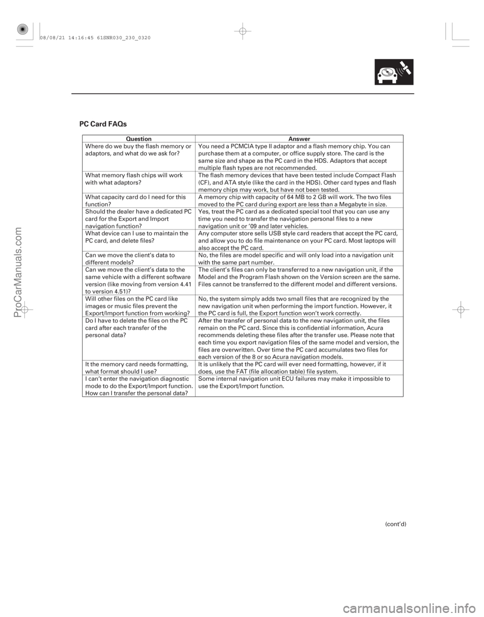
PC Card FAQs
QuestionAnswer
23-317
Wheredowebuytheflashmemoryor
adaptors, and what do we ask for?You need a PCMCIA type II adaptor and a flash memory chip. You can
purchase them at a computer, or office supply store. The card is the
same size and shape as the PC card in the HDS. Adaptors that accept
multiple flash types are not recommended.
What memory flash chips will work
with what adaptors? The flash memory devices that have been tested include Compact Flash
(CF), and ATA style (like the card in the HDS). Other card types and flash
memory chips may work, but have not been tested.
What capacity card do I need for this
function? A memory chip with capacity of 64 MB to 2 GB will work. The two files
moved to the PC card during export are less than a Megabyte in size.
Should the dealer have a dedicated PC
card for the Export and Import
navigation function? Yes, treat the PC card as a dedicated special tool that you can use any
time you need to transfer the navigation personal files to a new
navigation unit or ’09 and later vehicles.
What device can I use to maintain the
PC card, and delete files? Any computer store sells USB style card readers that accept the PC card,
and allow you to do file maintenance on your PC card. Most laptops will
also accept the PC card.
Can we move the client’s data to
different models? No, the files are model specific and will only load into a navigation unit
with the same part number.
Can we move the client’s data to the
same vehicle with a different software
version (like moving from version 4.41
to version 4.51)? The client’s files can only be transferred to a new navigation unit, if the
Model and the Program Flash shown on the Version screen are the same.
Files cannot be transferred to the different model and different versions.
Will other files on the PC card like
images or music files prevent the
Export/Import function from working? No, the system simply adds two small files that are recognized by the
new navigation unit when performing the import function. However, it
the PC card is full, the Export function won’t work correctly.
Do I have to delete the files on the PC
card after each transfer of the
personal data? After the transfer of personal data to the new navigation unit, the files
remain on the PC card. Since this is confidential information, Acura
recommends deleting these files after the transfer use. Please note that
each time you export navigation files of the same model and version, the
files are overwritten. Over time the PC card accumulates two files for
each version of the 8 or so Acura navigation models.
It the memory card needs formatting,
what format should I use? It is unlikely that the PC card will ever need formatting, however, if it
does, use the FAT (file allocation table) file system.
I can’t enter the navigation diagnostic
mode to do the Export/Import function.
How can I transfer the personal data? Some internal navigation unit ECU failures may make it impossible to
use the Export/Import function.
(cont’d)
08/08/21 14:16:45 61SNR030_230_0320
ProCarManuals.com
DYNOMITE -2009-
Page 2613 of 2893

����
�(�#�'�����#��� �����
�������#���������������)����
�´ �µ
�µ
�µ �µ
�µ
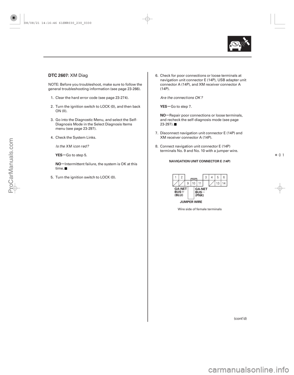
DTC 2607:
YES
NO YES
NO
23-327
NAVIGATION UNIT CONNECTOR E (14P)
GA-NET
BUS
(BLU) GA-NET
BUS
(PNK)
JUMPER WIRE
XM Diag
NOTE: Before you troubleshoot, make sure to follow the
general troubleshooting information (see page 23- 266).
1. Clear the hard error code (see page 23-274).
2. Turn the ignition switch to LOCK (0), and then back ON (II).
3. Go into the Diagnostic Menu, and select the Self- Diagnosis Mode in the Select Diagnosis Items
menu (see page 23-297).
4. Check the System Links.
Go to step 5.
Intermittent failure, the system is OK at this
time.
5. Turn the ignition switch to LOCK (0). 6. Check for poor connections or loose terminals at
navigation unit connector E (14P), USB adapter unit
connector A (14P), and XM receiver connector A
(14P).
Go to step 7.
Repair poor connections or loose terminals,
and recheck the self-diagnosis mode (see page
23-297).
7. Disconnect navigation unit connector E (14P) and XM receiver connector A (14P).
8. Connect navigation unit connector E (14P) terminals No. 9 and No. 10 with a jumper wire.
(cont’d)
Wire side of female terminals
Is the X M icon red? Ar e t he connect i ons OK ?
08/08/21 14:16:46 61SNR030_230_0330
ProCarManuals.com
DYNOMITE -2009-
Page 2614 of 2893

�´
�µ
�����
����� �����
�´
�µ
�´ �µ �´
�µ
�µ
�µ
�µ
�µ �µ
�µ
YES
NO
YES
NO YES
NO
23-328Navigation System
DTC Troubleshooting (cont’d)
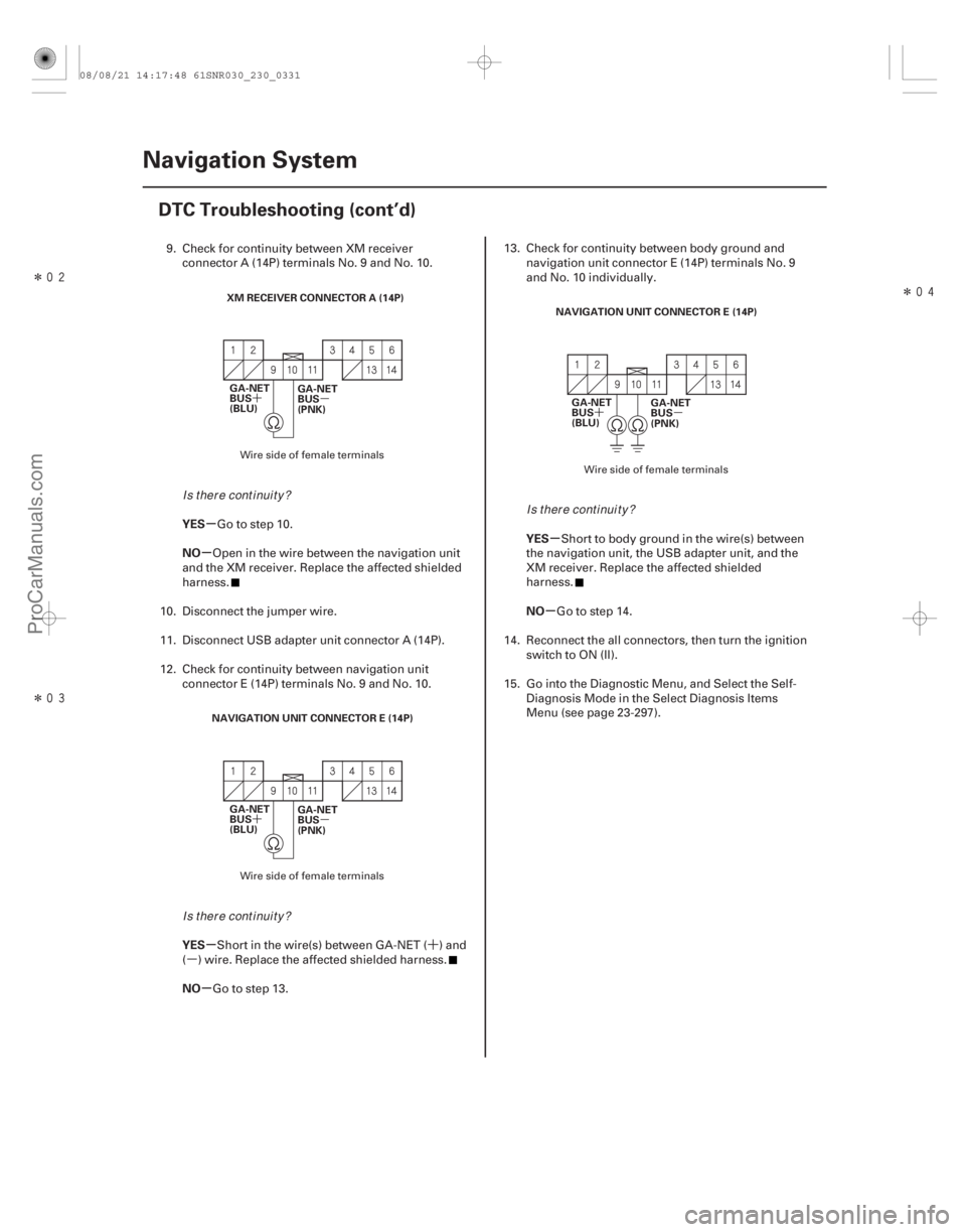
XM RECEIVER CONNECTOR A (14P)
GA-NET
BUS
(BLU) GA-NET
BUS
(PNK)
NAVIGATION UNIT CONNECTOR E (14P) GA-NET
BUS
(BLU) GA-NET
BUS
(PNK) NAVIGATION UNIT CONNECTOR E (14P)
GA-NET
BUS
(BLU) GA-NET
BUS
(PNK)
9. Check for continuity between XM receiver
connector A (14P) terminals No. 9 and No. 10.
Go to step 10.
Open in the wire between the navigation unit
and the XM receiver. Replace the affected shielded
harness.
10. Disconnect the jumper wire.
11. Disconnect USB adapter unit connector A (14P).
12. Check for continuity between navigation unit connector E (14P) terminals No. 9 and No. 10.
Short in the wire(s) between GA-NET ( ) and
( ) wire. Replace the affected shielded harness.
Go to step 13. 13. Check for continuity between body ground and
navigation unit connector E (14P) terminals No. 9
and No. 10 individually.
Short to body ground in the wire(s) between
the navigation unit, the USB adapter unit, and the
XM receiver. Replace the affected shielded
harness.
Go to step 14.
14. Reconnect the all connectors, then turn the ignition switch to ON (II).
15. Go into the Diagnostic Menu, and Select the Self- Diagnosis Mode in the Select Diagnosis Items
Menu (see page 23-297).
Wire side of female terminals
Wire side of female terminals Wire side of female terminals
Is there continuity?
Is there continuity? Is there continuity?
08/08/21 14:17:48 61SNR030_230_0331
ProCarManuals.com
DYNOMITE -2009-
Page 2615 of 2893

�(�#�'�����#��� �����
�������#���������������)����
�µ
�µ
�µ
�µ
�µ
�µ �µ
�µ
YES
NO
YES
NO
YES
NO YES
NO
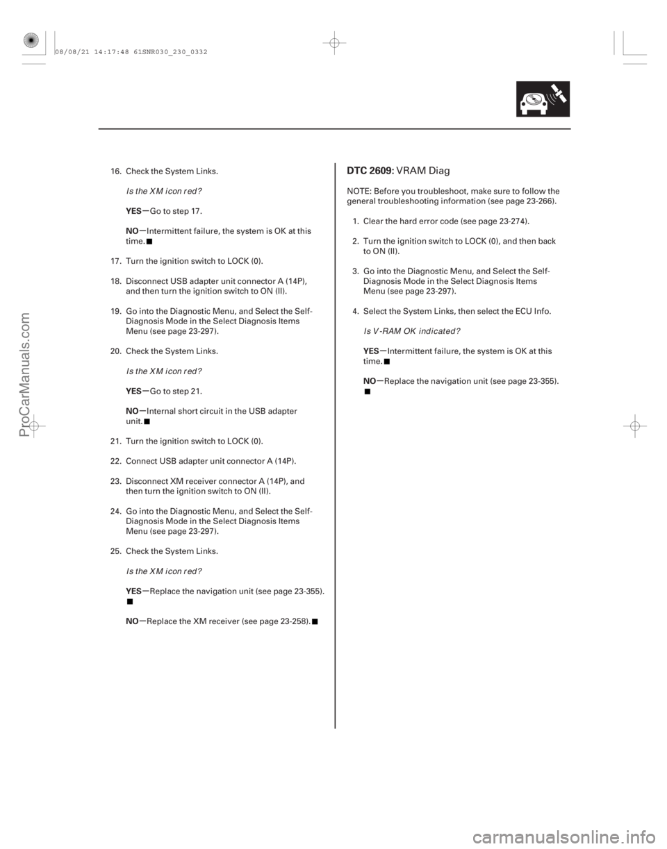
DTC 2609:
23-32923-329
16. Check the System Links.
Go to step 17.
Intermittent failure, the system is OK at this
time.
17. Turn the ignition switch to LOCK (0).
18. Disconnect USB adapter unit connector A (14P), and then turn the ignition switch to ON (II).
19. Go into the Diagnostic Menu, and Select the Self- Diagnosis Mode in the Select Diagnosis Items
Menu (see page 23-297).
20. Check the System Links.
Go to step 21.
Internal short circuit in the USB adapter
unit.
21. Turn the ignition switch to LOCK (0).
22. Connect USB adapter unit connector A (14P).
23. Disconnect XM receiver connector A (14P), and then turn the ignition switch to ON (II).
24. Go into the Diagnostic Menu, and Select the Self- Diagnosis Mode in the Select Diagnosis Items
Menu (see page 23-297).
25. Check the System Links.
Replace the navigation unit (see page 23-355).
Replace the XM receiver (see page 23-258). NOTE: Before you troubleshoot, make sure to follow the
general troubleshooting information (see page 23-266).
1. Clear the hard error code (see page 23-274).
2. Turn the ignition switch to LOCK (0), and then back to ON (II).
3. Go into the Diagnostic Menu, and Select the Self- Diagnosis Mode in the Select Diagnosis Items
Menu (see page 23-297).
4. Select the System Links, then select the ECU Info.
Intermittent failure, the system is OK at this
time.
Replace the navigation unit (see page 23-355).VRAM Diag
Is the X M icon red?
Is the X M icon red?
Is the X M icon red? I s V -RAM OK i nd i cat ed ?
08/08/21 14:17:48 61SNR030_230_0332
ProCarManuals.com
DYNOMITE -2009-