Page 2449 of 2893
")
����
Contents Audio output
Left front CH Right front CH Right rear CH Left rear CH Subwoofer CH
USB Adapter
GA-Net Bus Configuration
23-165
Navigation unit
or audio unit
Accessory
(CD changer etc.)
XM Receiver
USB Adapter
(With navigation)
The navigation system allows voice control of the audio, XM, PC card, and CD player. Voice control commands are
communicated on the GA-Net (audio unit). When using the navigation TALK/BACK button, the audio is muted on all
speakers and you get navigation sound on the front channels. When using the navigation or route guidance (RG), the
front speakers give the navigation sound and the rear speakers continue to play. For more information, see the
navigation section. The outline of the interruption function is shown in this table.
Navigation TALK/BACK Buttons Navigation voice
output Navigation voice
output Muted Muted Muted
Route guidance Navigation voice outputNavigation voice
output Audio Audio Audio
The audio unit can play digital music from portable audio players, USB drive, etc. When the device is plugged into the
USB adapter. The audio unit uses the GA-NET to allow you to control the device from the audio unit when searching
and playing the files. Not all players and player functions work with the USB adapter. Please see the owner’s manual
for more information.
The GA-Net bus passes audio and navigation commands throughout the navigation and audio components.
These commands include navigation touch screen and hard button signals, audio/XM selections by voice, and XM
station and music title names. Because the entire bus is daisy chained between components (see diagram), any open
or short in the GA-Net bus harness will cause any or all of these functions to become inoperative. Naturally the
addition of any audio accessory must maintain the continuity of the GA-Net bus by installing the Y cable included with
the accessory kit.
(cont’d)
08/08/21 14:08:46 61SNR030_230_0168
ProCarManuals.com
DYNOMITE -2009-
Page 2450 of 2893
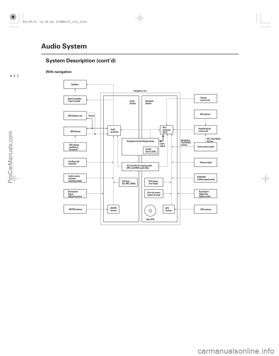
�����With navigation
23-166Audio System
System Description (cont’d)
Reverse signal
GPS antenna
AM/FM antenna Speakers
Navigation unit
Navi DVD
Navigation/Audio Display Screen
CLOCK
(Set by GPS)Color
signal
XM antenna
(satellite &
terrestrial)
Auxiliary jack
assembly
Audio remote
switches
(steering wheel)
Illumination
Signal
(lighted buttons)
AM/FM
receiverCD Player
(CD, MP3, WMA)
Audio
processor
PC Card Slot (for playing audio
MP3, and WMA audio files) Navi
processor
(ECU)
GPS
receiver
Yaw rate sensor
(senses turning)
DVD player
(navi maps)
GA-net
Audio
Section
Navigaion
Section
Illumination
(Night/Day
display mode)
ECM/PCM
(vehicle speed pulses) Voice control switch
USB Adapter unit
XM Receiver HandsFreeLink
control unitMicrophone
HFL TALK/BACK
buttons
Navigation
TALK/BACK
buttons
Stereo Amplifier
(Type S model)
Climate
control unit
08/08/21 14:08:46 61SNR030_230_0169
ProCarManuals.com
DYNOMITE -2009-
Page 2453 of 2893

Audio GlossaryItem Definition
23-169
Track A sound recording on a CD, tape, or PC Card.
Treble An adjustment to control the volume of the high frequency sounds.
Tuner A component (or part of a component) that receives radio signals and selects
one broadcast from many.
Tweeter A speaker designed to reproduce the higher frequencies (treble) only.
USB Universal Serial Bus. The USB is used for playing the compressed audio files
(MP3, WMA, and AAC) on the external device through the audio unit.
Voice coil A coil of wire wrapped around a tube and then attached to the speaker cone or
diaphragm. When an audio signal is applied, the coil becomes an
electromagnet and interacts with the permanent magnet causing the come or
diaphragm to vibrate. We interpret this vibrations as sound.
Volume control Allows you to control the loudness of the music.
WMA music file Windows Media Audio File. This is an accepted format for music files to be
played on either a CD-R, a CD-RW or a PC Card.
Woofer A speaker that is designed to reproduce low (bass) frequencies only.
XM radio Satellite based radio transmission, which also uses a ground based repeater
network to ensure seamless reception. The channels originate from XM’s
broadcast center, in Washington, DC, and uplink to two satellites. These
satellites transmit the signal across the entire continental United States.
XM receiver The external component that receives and processes the XM signals from the
XM satellites, and terrestrial (land) stations. The audio unit communicates to
the XM receiver over the GA-Net bus.
(cont’d)
08/08/21 14:08:47 61SNR030_230_0172
ProCarManuals.com
DYNOMITE -2009-
Page 2457 of 2893

Cavity Wire Color Connect to NAVIGATION UNIT CONNECTOR G (3P)
Cavity Wire Color")
�´�´
�´ �´
�µ
�µ
�µ
�•�•�•
�•�•�•
�•�•�• �´
�����
�����
NAVIGATION UNIT CONNECTOR E (14P)
Cavity Wire Color Connect to NAVIGATION UNIT CONNECTOR G (3P)
Cavity Wire Color Connect to
23-173
E1 BLU XM receiver, USB adapter unit
(B)
E2 LT BLU XM receiver, USB adapter unit (SYS ACC)
E3 BRN Shield for terminals No. 9 and No. 10 (GA-NET BUS SH)
E4 GRY Shield for terminals No. 5, No. 6, No. 13, and No. 14
(SAT SH GND)
E5 WHT XM receiver, USB adapter unit (AUDIO R )
E6 RED XM receiver, USB adapter unit (AUDIO L )
E9 BLU XM receiver, USB adapter unit (GA-NET BUS )
E10 PNK XM receiver, USB adapter unit (GA-NET BUS )
E11 BLK XM receiver, USB adapter unit (GA-NET GND)
E13 BLK XM receiver, USB adapter unit (AUDIO R )
E14 GRN XM receiver, USB adapter unit (AUDIO L )
: The shielded wires have a heat-shrink tube insulating the outside of the wire. The color of the
insulating tube, typically black or dark gray, may
not match the color of the wire listed on the
schematic. G1 AM/FM/XM antenna (RF IN)
G2 Shield for terminal No. 1
(RF SH)
G3 AM/FM/XM antenna (ANT B)
(cont’d)
Wire side of female terminals Terminal side of female terminals
08/08/21 14:08:48 61SNR030_230_0176
ProCarManuals.com
DYNOMITE -2009-
Page 2460 of 2893

Cavity Wire Color Connect to AUDIO UNIT CONNECTOR G (3P)
Cavity Wire Color Connect to")
�´�´
�´
�´
�µ �µ
�µ�•�•�•
�•�•�•
�•�•�• �´
��
�
��
��
AUDIO UNIT CONNECTOR E (14P)
Cavity Wire Color Connect to AUDIO UNIT CONNECTOR G (3P)
Cavity Wire Color Connect to
23-176Audio System
System Description (cont’d)
E1 BLU USB adapter unit ( B)
E2 LT BLU USB adapter unit (SYS ACC)
E3 BRN Shield for terminals No. 9 and
No. 10 (BUS SH GND)
E4 GRY Shield for terminals No. 5, No. 6, No. 13, and No. 14
(SAT SH GND)
E5 WHT USB adapter unit (SAT R )
E6 RED USB adapter unit (SAT L )
E9 BLU USB adapter unit (GA-NET BUS )
E10 PNK USB adapter unit (GA-NET BUS )
E11 BLK USB adapter unit (GND)
E13 BLK USB adapter unit (SAT R )
E14 GRN USB adapter unit (SAT L )
: The shielded wires have a heat-shrink tube insulating the outside of the wire. The color of the
insulating tube, typically black or dark gray, may
not match the color of the wire listed on the
schematic. G1 AM/FM antenna (RF IN)
G2 Shield for terminal No. 1
(RF SH)
G3 AM/FM antenna (ANT B)
Wire side of female terminals Terminal side of female terminals
08/08/21 14:08:48 61SNR030_230_0179
ProCarManuals.com
DYNOMITE -2009-
Page 2464 of 2893

Cavity Wire Color Connect to XM RECEIVER CONNECTOR B (2P)
Cavity Wire Color Connect to
23-180Audio Sy")
�´�´
�´ �´
�µ
�µ
�µ
�•�•�•
�•�•�•
��
��
��
��
XM RECEIVER CONNECTOR A (14P)
Cavity Wire Color Connect to XM RECEIVER CONNECTOR B (2P)
Cavity Wire Color Connect to
23-180Audio System
System Description (cont’d)
A1 BLU Navigation unit, USB adapter
unit ( B)
A2 LT BLU Navigation unit, USB adapter unit (SYS ACC)
A3 BRN Shield for terminals No. 9 and No. 10 (GA-NET SH GND)
A5 WHT Navigation unit, USB adapter unit (SAT R )
A6 RED Navigation unit, USB adapter unit (SAT L )
A9 BLU Navigation unit, USB adapter unit (GA-NET BUS )
A10 PNK Navigation unit, USB adapter unit (GA-NET BUS )
A11 BLK Navigation unit, USB adapter unit (GND)
A13 BLK Navigation unit, USB adapter unit (SAT R )
A14 GRN Navigation unit, USB adapter unit (SAT L )
: The shielded wires have a heat-shrunk tube insulating the outside of the wire. The color of the
insulating tube, typically black or dark gray, may
not match the color of the wire listed on the
schematic. B1 Satellite signal antenna (SAT/
TER)
B2 Shield for terminal No. 1 (GND SH)
Wire side of female terminals Terminal side of female terminals
08/08/21 14:09:43 61SNR030_230_0183
ProCarManuals.com
DYNOMITE -2009-
Page 2465 of 2893
��
��
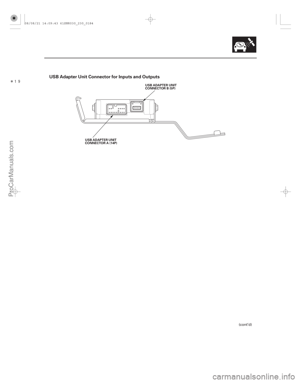
USB Adapter Unit Connector for Inputs and Outputs
23-181
USB ADAPTER UNIT
CONNECTOR A (14P)USB ADAPTER UNIT
CONNECTOR B (5P)
(cont’d)
08/08/21 14:09:43 61SNR030_230_0184
ProCarManuals.com
DYNOMITE -2009-
Page 2466 of 2893

Cavity Wire Color Connect to USB ADAPTER
UNIT CON")
�´�´
�´ �´
�µ
�µ
�µ
�•�•�•
�•�•�• �µ
�•�•�• �´
�•�•�•
�•�•�•
�����
����
USB ADAPTER
UNIT CONNECTOR A (14P)
Cavity Wire Color Connect to USB ADAPTER
UNIT CONNECTOR B (5P)
Cavity Wire Color Connect to
23-182Audio System
System Description (cont’d)
A1 BLU Navigation unit , audio unit ,
XM receiver ( B)
A2 LT BLU Navigation unit , audio unit , XM receiver (SYS ACC)
A3 BRN Shield for terminals No. 9 and No. 10 (GA-NET BUS SH)
A4 GRY Shield for terminals No. 5, No. 6, No. 13, and No. 14
(AUDIO SH)
A5 WHT Navigation unit , audio unit , XM receiver (AUDIO R )
A6 RED Navigation unit , audio unit , XM receiver (AUDIO L )
A9 BLU Navigation unit , audio unit , XM receiver (GA-NET BUS )
A10 PNK Navigation unit , audio unit , XM receiver (GA-NET BUS )
A11 BLK Navigation unit , audio unit , XM receiver (GND)
A13 BLK Navigation unit , audio unit , XM receiver (AUDIO R )
A14 GRN Navigation unit, XM receiver (AUDIO L )
1: The shielded wires have a heat-shrunk tube insulating the outside of the wire. The color of the
insulating tube, typically black or dark gray, may
not match the color of the wire listed on the
schematic.
2: With navigation
3: Without navigation B1 USB adapter (USB VBUS)
B2 USB adapter (USB DATA )
B3 USB adapter (USB DATA )
B4 USB adapter (USB GND)
B5 Shield for terminals No. 1,
No.2,No.3,andNo.4(USB
SH)23
23
1
1
23
23
23
23
23
23
Wire side of female terminals Terminal side of female terminals
08/08/21 14:09:44 61SNR030_230_0185
ProCarManuals.com
DYNOMITE -2009-