Page 1817 of 2893
����
���
�(�#�'���������������
�������
��������� �����)����
Special Tools Required
20-13720-137
Rear Seat Armrest Beverage Holder
Replacement
A B
C
D
D
AB
C
D
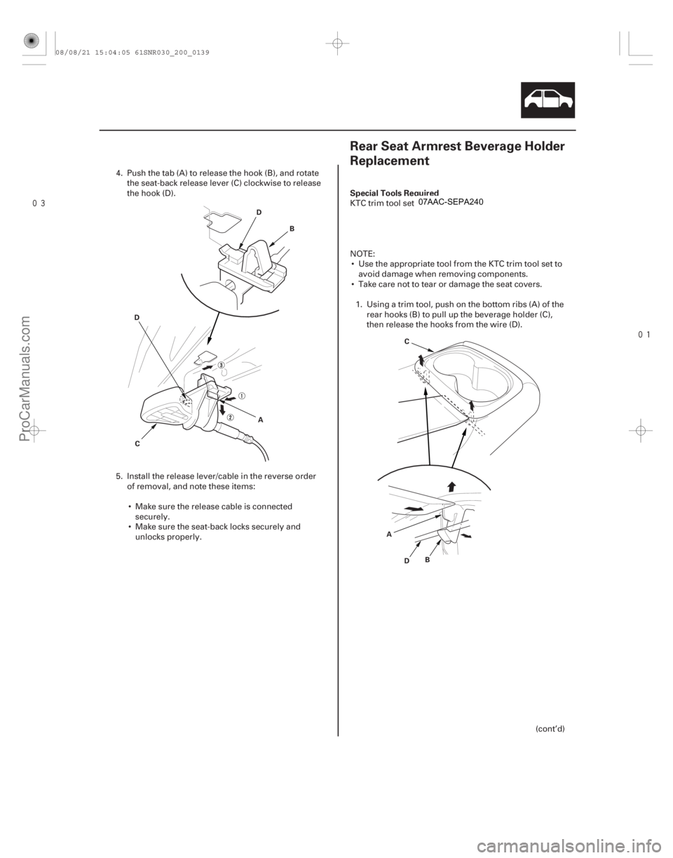
4. Push the tab (A) to release the hook (B), and rotate the seat-back release lever (C) clockwise to release
the hook (D).
5. Install the release lever/cable in the reverse order of removal, and note these items:
Make sure the release cable is connected securely.
Make sure the seat-back locks securely and unlocks properly. KTC trim tool set SOJATP2014
NOTE:
Use the appropriate tool from the KTC trim tool set to avoid damage when removing components.
Take care not to tear or damage the seat covers.
1. Using a trim tool, push on the bottom ribs (A) of the rear hooks (B) to pull up the beverage holder (C),
then release the hooks from the wire (D).
(cont’d)
08/08/21 15:04:05 61SNR030_200_0139
ProCarManuals.com
DYNOMITE -2009-
Page 1818 of 2893
����
���
�(�#�'���������������
�������
��������� �����)����
Special Tools Required
20-13720-137
Rear Seat Armrest Beverage Holder
Replacement
A B
C
D
D
AB
C
D
4. Push the tab (A) to release the hook (B), and rotate the seat-back release lever (C) clockwise to release
the hook (D).
5. Install the release lever/cable in the reverse order of removal, and note these items:
Make sure the release cable is connected securely.
Make sure the seat-back locks securely and unlocks properly. KTC trim tool set SOJATP2014
NOTE:
Use the appropriate tool from the KTC trim tool set to avoid damage when removing components.
Take care not to tear or damage the seat covers.
1. Using a trim tool, push on the bottom ribs (A) of the rear hooks (B) to pull up the beverage holder (C),
then release the hooks from the wire (D).
(cont’d)
08/08/21 15:04:05 61SNR030_200_0139
ProCarManuals.com
DYNOMITE -2009-
Page 1844 of 2893
���
����
����
�(�#�'�����������
��������������������� �����)����
20-159
Fuel Cap Adapter Replacement
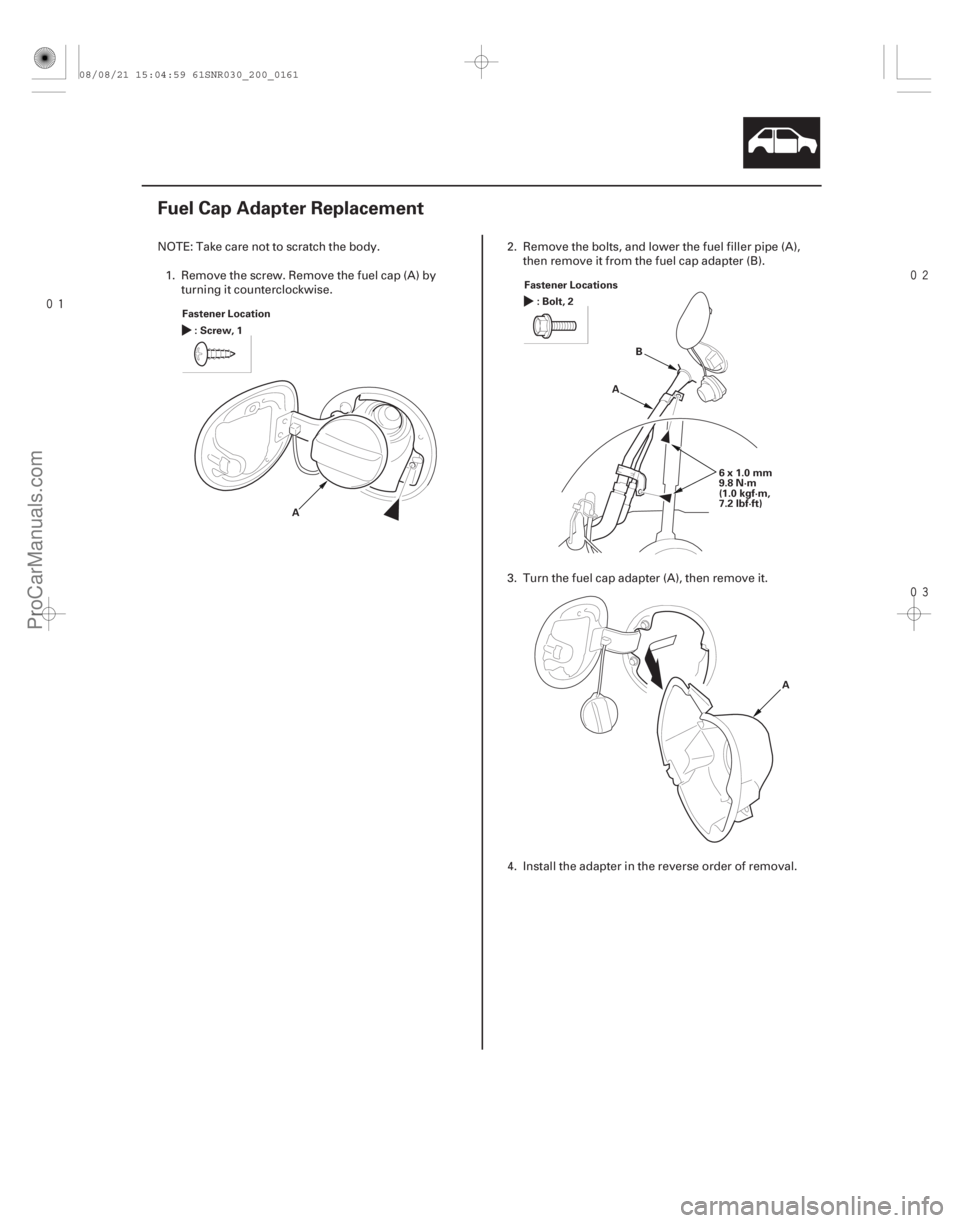
Fastener Location :Screw,1
A Fastener Locations
:Bolt,2
AB
6x1.0mm
9.8 N·m
(1.0 kgf·m,
7.2 lbf·ft)
A
NOTE: Take care not to scratch the body.1. Remove the screw. Remove the fuel cap (A) by turning it counterclockwise. 2. Remove the bolts, and lower the fuel filler pipe (A),
then remove it from the fuel cap adapter (B).
3. Turn the fuel cap adapter (A), then remove it.
4. Install the adapter in the reverse order of removal.
08/08/21 15:04:59 61SNR030_200_0161
ProCarManuals.com
DYNOMITE -2009-
Page 2014 of 2893
�����µ �µ�µ
Disconnection Reconnection
22-68Battery
Battery Terminal Disconnection and Reconnection
B
A
2.9 5.9 N·m
(0.3 0.6 kgf·m, 2.1 4.4 l")
����
�(�#�'�����������������������
�������
�"�����)�����µ �µ�µ
Disconnection Reconnection
22-68Battery
Battery Terminal Disconnection and Reconnection
B
A
2.9 5.9 N·m
(0.3 0.6 kgf·m, 2.1 4.4 lbf·ft)
C
Some systems store data in memory that is lost when
the battery is disconnected. Do the following steps
before disconnecting the battery.1. Make sure you have the anti-theft code(s) for the audio and/or the navigation system (if equipped).
2. If you are replacing the audio unit, write down the audio presets (AM and FM), and the XM audio
presets (if equipped), because the audio unit does
not retain the presets after the battery is
disconnected.
3. Make sure the ignition switch is in LOCK (0).
4. Disconnect and isolate the negative cable from the battery.
NOTE: Always disconnect the negative cable from
the battery first.
5. Disconnect the positive cable from the battery. Some systems store data in memory that is lost when
the battery is disconnected. Do the following steps to
restore the systems back to normal operation.
1. Clean the battery terminals.
2. Test the battery (see page 22-67).
3. Reconnect the positive cable (A) to the battery (B) first, then reconnect the negative cable (C) to the
battery.
NOTE: Always connect the positive cable to the
battery first.
4. Apply multipurpose grease to the terminals to prevent corrosion.
5. Enter the anti-theft code(s) for the audio system and/or the navigation system (if equipped).
6. Enter the audio presets (if applicable), and enter the XM audio presets (if equipped).
7. Set the clock (for vehicles without navigation).
08/08/21 14:24:04 61SNR030_220_0070
ProCarManuals.com
DYNOMITE -2009-
Page 2116 of 2893
����
22-168 Exterior Lights
HID Bulb Replacement
A
C B A
A transient high tension (25,000 V) occurs at the
bulb sockets of the high intensity di")
���
����
�(�#�'�����!���������
�����
�
��������� �����)����
22-168 Exterior Lights
HID Bulb Replacement
A
C B A
A transient high tension (25,000 V) occurs at the
bulb sockets of the high intensity discharge (HID)
lamps when the combination light switch is turned
ON. It may cause serious electrical shock or
electrocution if you do not observe the cautions.
Never turn on the combination light switch before fitting the HID bulbs to their bulb sockets
and completing the reassembly of the headlight
assembly.
Do not service the headlight assembly in wet conditions, such as rain or snow, near a sprinkler
system, or when your hands are wet to prevent
electrocution.
Do not touch the surface of the HID bulbs with your bare hands and do not stain it with any oils
and fats.
Do not disassemble the inverter unit and the igniter fats.
Do not turn on the HID bulb by using a power source other than the battery mounted on your
vehicle.
1. Turn the combination light switch OFF.
2. Do the battery terminal disconnection procedure (see page 22-68).
3. Remove the battery. (left side bulb) 4. Turn the cover (A) 45 ° counterclockwise to remove
it from the headlight assembly.
5. Turn the socket (A) 45 ° counterclockwise to remove it from the bulb (B).
6. Pull the retaining spring (C) away from the bulb then remove the bulb.
7. Install the new bulb in the reverse order of removal. Make sure the notches in the bulb align with the
tabs in the headlight.
8. Install the parts in the reverse order of removal.
9. Do the battery terminal reconnection procedure (see page 22-68).
08/08/21 14:26:59 61SNR030_220_0170
ProCarManuals.com
DYNOMITE -2009-
Page 2124 of 2893
���� ����
�����
�(�#����������������
�����
�����
���
� �����)����
’07-08 models ’09 model
FOG LIGHT: 55 W FOG LIGHT: 55 W
22-17522-175")
���
�����(�#�'�������%�������
�����
�����
���
� �����)���� ����
�����
�(�#�'���������������
�����
�����
���
� �����)����
’07-08 models ’09 model
FOG LIGHT: 55 W FOG LIGHT: 55 W
22-17522-175
Fog Light Replacement
AB
A A
B
A
1. Remove the fog light cover.
2. Remove the mounting screw from the fog light.
3. Remove the fog light (A) from the front bumper.
4. Disconnect the 2P connector (B) from the fog light.
5. Turn the bulb socket (A) 60 ° counterclockwise to remove it from the housing.
6. Install the fog light in the reverse order of removal.
7. After replacement, adjust the fog lights to local requirements (see page 22-176). 1. Remove the mounting screw from the fog light.
2. Remove the fog light (A) from the front bumper.
3. Disconnect the 2P connector (B) from the fog light.
4. Turn the bulb socket (A) 60 ° counterclockwise to
remove it from the housing.
5. Install the fog light in the reverse order of removal.
6. After replacement, adjust the fog lights to local requirements (see page 22-176).
08/08/21 14:27:02 61SNR030_220_0177
ProCarManuals.com
DYNOMITE -2009-
Page 2126 of 2893
����
���
����
�(�#�'���������������
�����
�
��������� �����)����
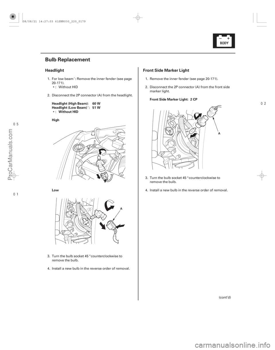
Headlight Front Side Marker Light
Headlight (High Beam): 60 W
Headlight (Low Beam) : 51 W
Without HID
High
Low Front Side Marker Light: 2 CP
22-177
Bulb Replacement
A
A
1. For low beam : Remove the inner fender (see page
20-171).: Without HID
2. Disconnect the 2P connector (A) from the headlight.
:
3. Turn the bulb socket 45 ° counterclockwise to remove the bulb.
4. Install a new bulb in the reverse order of removal. 1. Remove the inner fender (see page 20-171).
2. Disconnect the 2P connector (A) from the front side
marker light.
3. Turn the bulb socket 45 ° counterclockwise to remove the bulb.
4. Install a new bulb in the reverse order of removal.
(cont’d)
08/08/21 14:27:03 61SNR030_220_0179
ProCarManuals.com
DYNOMITE -2009-
Page 2127 of 2893
��������
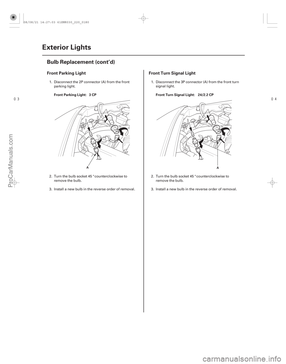
Front Parking LightFront Turn Signal Light
Front Parking Light: 3 CP Front Turn Signal Light: 24/2.2 CP
22-178Exterior Lights
Bulb Replacement (cont’d)
A
A
1. Disconnect the 2P connector (A) from the front
parking light.
2. Turn the bulb socket 45 ° counterclockwise to remove the bulb.
3. Install a new bulb in the reverse order of removal. 1. Disconnect the 3P connector (A) from the front turn
signal light.
2. Turn the bulb socket 45 ° counterclockwise to remove the bulb.
3. Install a new bulb in the reverse order of removal.
08/08/21 14:27:03 61SNR030_220_0180
ProCarManuals.com
DYNOMITE -2009-