Page 1170 of 2893
���
��������
����
�(�#�'�������
���
�����
�
���
��������� �����)����
14-254 Automatic Transmission
Shift Lever Removal
A
A
B C
A
B
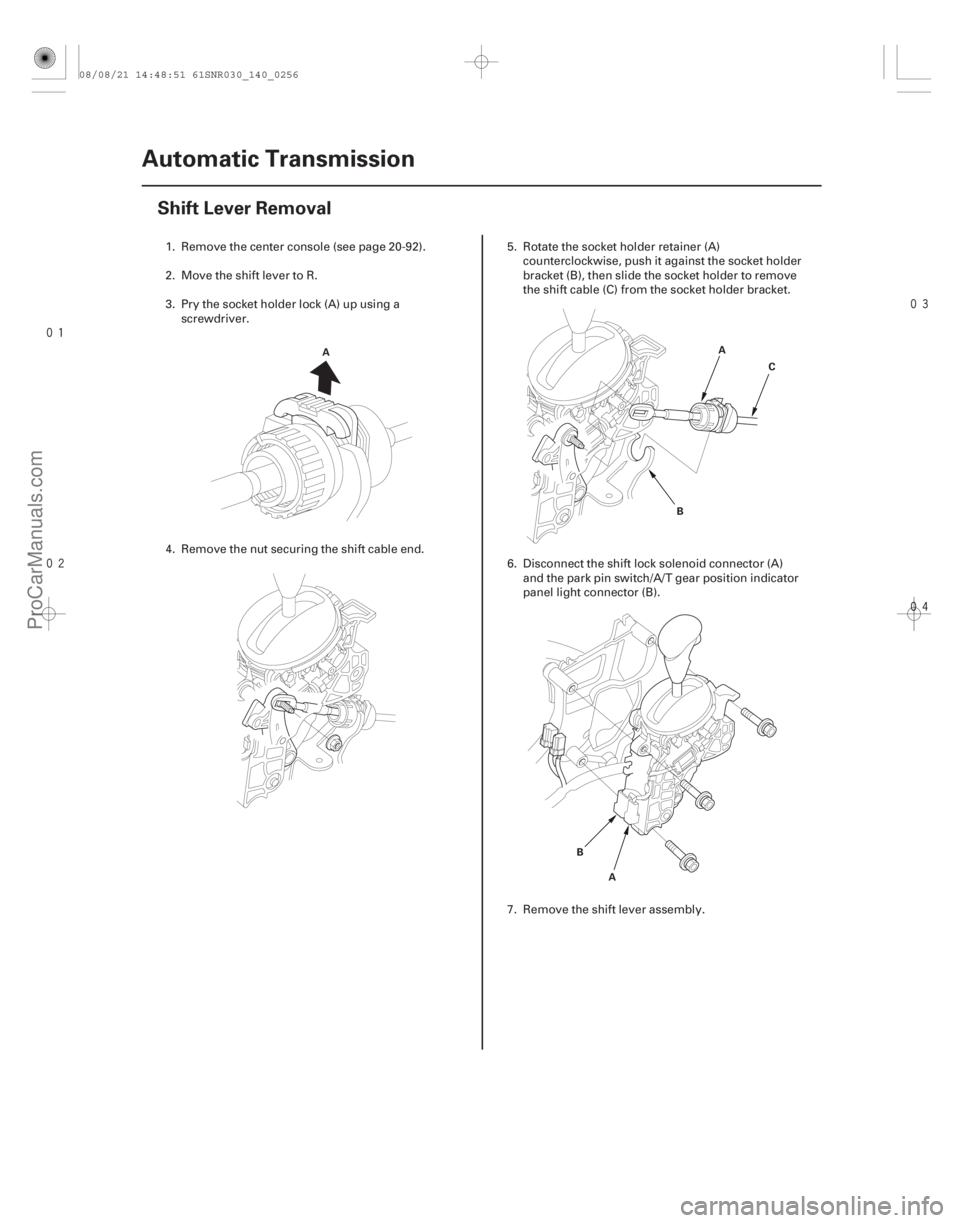
1. Remove the center console (see page 20-92).
2. Move the shift lever to R.
3. Pry the socket holder lock (A) up using a
screwdriver.
4. Remove the nut securing the shift cable end. 5. Rotate the socket holder retainer (A)
counterclockwise, push it against the socket holder
bracket (B), then slide the socket holder to remove
the shift cable (C) from the socket holder bracket.
6. Disconnect the shift lock solenoid connector (A) and the park pin switch/A/T gear position indicator
panel light connector (B).
7. Remove the shift lever assembly.
08/08/21 14:48:51 61SNR030_140_0256
ProCarManuals.com
DYNOMITE -2009-
Page 1173 of 2893
����
14-257
Shift Cable Replacement
A A
B C
A BC
D
E
F
1. Raise the vehicle on a lift, or apply the parking
brake, block the rear wheel")
���
��������
����
�(�#�'�������
���
�����
�
���
�������
� �����)����
14-257
Shift Cable Replacement
A A
B C
A BC
D
E
F
1. Raise the vehicle on a lift, or apply the parking
brake, block the rear wheels, and raise the front of
the vehicle. Make sure it is securely supported.
2. Move the shift lever to R.
3. Remove the center console (see page 20-92).
4. Pry the socket holder lock (A) up using a screwdriver.
5. Remove the nut securing the shift cable end. 6. Rotate the socket holder retainer (A)
counterclockwise, push it against the socket holder
bracket (B), then slide the socket holder to remove
the shift cable (C) from the socket holder bracket.
7. Remove the three bolts securing the shift cable holder (A), then remove the shift cable cover (B).
8. Pry up the lock tab of the lock washer (C), and remove the lock bolt (D) and the lock washer, then
separate the control lever (E) from the selector
control shaft (F). Do not bend the shift cable
excessively.
(cont’d)
08/08/21 14:48:52 61SNR030_140_0259
ProCarManuals.com
DYNOMITE -2009-
Page 1175 of 2893
���
��������
����
�(�#�'�������
���
�����
�
���
�������
�"�����)����
14-259
Shift Cable Adjustment
A A
B C
A
B C
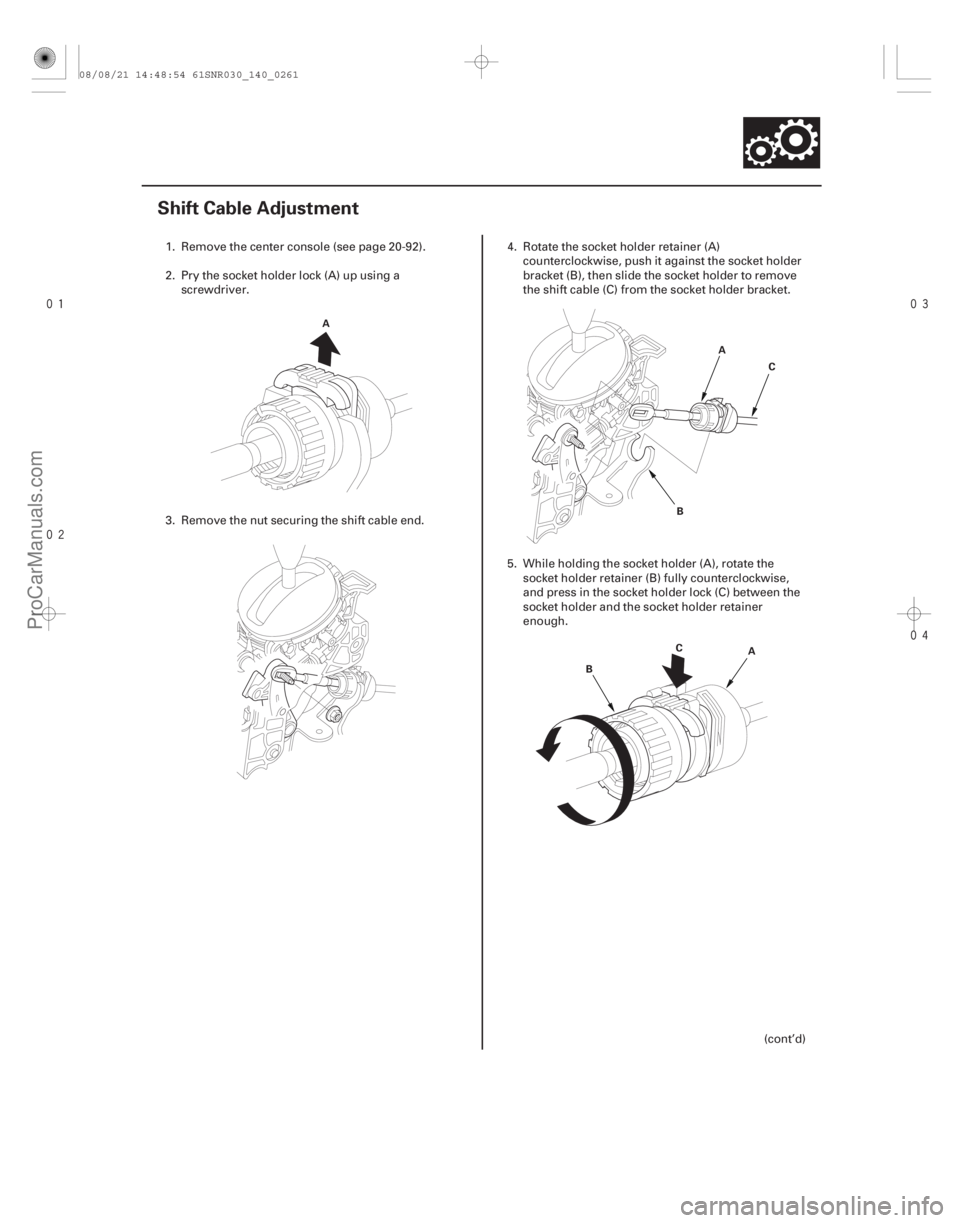
1. Remove the center console (see page 20-92).
2. Pry the socket holder lock (A) up using a
screwdriver.
3. Remove the nut securing the shift cable end. 4. Rotate the socket holder retainer (A)
counterclockwise, push it against the socket holder
bracket (B), then slide the socket holder to remove
the shift cable (C) from the socket holder bracket.
5. While holding the socket holder (A), rotate the socket holder retainer (B) fully counterclockwise,
and press in the socket holder lock (C) between the
socket holder and the socket holder retainer
enough.
(cont’d)
08/08/21 14:48:54 61SNR030_140_0261
ProCarManuals.com
DYNOMITE -2009-
Page 1176 of 2893
����
��������
����
14-260Automatic Transmission
Shift Cable Adjustment (cont’d)
A
B
C
A B
C B
A
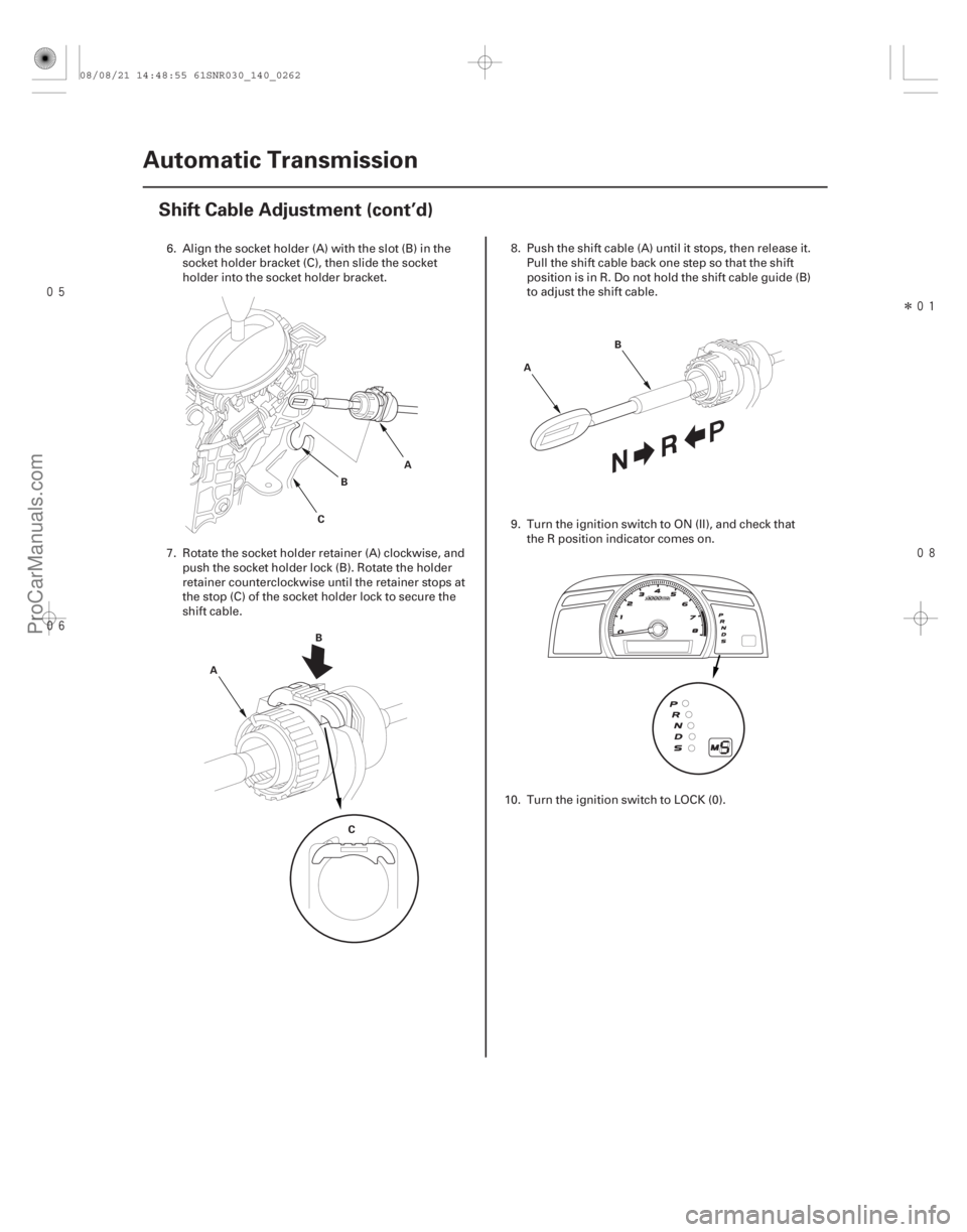
6. Align the socket holder (A) with the slot (B) in the socket holder bracket (C), then slide the socket
holder into the socket holder bracket.
7. Rotate the socket holder retainer (A) clockwise, and push the socket holder lock (B). Rotate the holder
retainer counterclockwise until the retainer stops at
the stop (C) of the socket holder lock to secure the
shift cable. 8. Push the shift cable (A) until it stops, then release it.
Pull the shift cable back one step so that the shift
position is in R. Do not hold the shift cable guide (B)
to adjust the shift cable.
9. Turn the ignition switch to ON (II), and check that the R position indicator comes on.
10. Turn the ignition switch to LOCK (0).
08/08/21 14:48:55 61SNR030_140_0262
ProCarManuals.com
DYNOMITE -2009-
Page 1341 of 2893
����
17-8 Steering
Steering Wheel Installation
A
B
A D
B
C A
39 N·m
(4.0 kgf·m,
29 lbf·ft)
B
1. Before installing the steering wheel, mak")
���
��������
�(�#�'���������������������������
���
� �����)����
17-8 Steering
Steering Wheel Installation
A
B
A D
B
C A
39 N·m
(4.0 kgf·m,
29 lbf·ft)
B
1. Before installing the steering wheel, make sure the front wheels are aligned straight ahead, then center
the cable reel (A). Do this by first rotating the cable
reel clockwise until it stops. Then rotate it
counterclockwise about three full turns. The arrow
mark (B) on the cable reel label should point
straight up.
2. Position the two tabs (A) of the turn signal canceling sleeve (B) as shown. Install the steering
wheel on to the steering column shaft, making sure
the steering wheel hub (C) engages the pins (D) of
the cable reel and tabs of the turn signal canceling
sleeve. Do not tap on the steering wheel or steering
column shaft when installing the steering wheel. 3. Install the steering wheel bolt (A), and tighten it to
the specified torque. Connect the cable reel
subharness connector (B). Make sure the wire
harness is routed and fastened properly.
4. Install the driver’s airbag, and confirm that the system is operating properly (see page 24-188).
5. Do the battery terminal reconnection procedure (see page 22-68), and do these tasks:
Turn the ignition switch to ON (II), and check that the SRS indicator comes on for about 6 seconds
and then goes off.
Make sure the horn and turn signal switches work properly.
Make sure the steering wheel is centered.
6. After installation, check the steering wheel spoke angle. If the steering spoke angles to the right and
left are not equal (steering wheel is not centered),
correct the engagement of the wheel/column shaft
serrations.
08/08/21 14:53:15 61SNR030_170_0009
ProCarManuals.com
DYNOMITE -2009-
Page 1497 of 2893
�
��
Pedal Height
Standard pedal height (with carpet removed): M/T: 153 mm (6.02 in.)
A/T: 158 mm (6.22 in.) Brake Pedal Position Switc")
���
��������
���
�(�#�'�����������
�����������
�������
�"�����)�
��
Pedal Height
Standard pedal height (with carpet removed): M/T: 153 mm (6.02 in.)
A/T: 158 mm (6.22 in.) Brake Pedal Position Switch Clearance
19-6Conventional Brake Components
Brake Pedal and Brake Pedal Position Switch Adjustment
A
B
B C
90 ° A
15 N·m
(1.5 kgf·m,
11 lbf·ft)B
Lower
the pedal Raise
the pedal
A
B
0.7 mm (0.028 in.)
1. Turn the brake pedal position switch (A) counterclockwise, and pull it back until it is no
longer touching the brake pedal.
2. Pull back the carpet, and find the cutout in the insulation. Measure the pedal height (B) at the
middle of the left side center of the pedal pad (C) to
the floor without the insulation. 3. Loosen the pushrod locknut (A), and screw the
pushrod (B) in or out with pliers until the standard
pedal height from the floor is reached. After
adjustment, tighten the locknut firmly. Do not
adjust the pedal height with the pushrod pressed.
4. Lift up on the brake pedal by hand. Push in the brake pedal position switch until its plunger is fully
pressed (threaded end (A) touching the pad (B) on
the pedal arm). Turn the switch 45 ° clockwise to
lock it. The gap between the brake pedal position
switch and the pad is automatically adjusted to
0.7mm(0.028in.)bylockingtheswitch.Makesure
the brake lights go off when the pedal is released.
5. Check the brake pedal free play.
08/08/21 15:00:50 61SNR030_190_0006
ProCarManuals.com
DYNOMITE -2009-
Page 1523 of 2893
D
8x1.0mm
23 N·m
(2.3 kgf·m,
17 lbf·ft)
A B
C
14. Rotate the caliper piston (A) clockwise into the
cylinder, then align the cutout (B) in the p")
����
19-31
E
8x1.25mm
22 N·m
(2.2 kgf·m, 16 lbf·ft)D
8x1.0mm
23 N·m
(2.3 kgf·m,
17 lbf·ft)
A B
C
14. Rotate the caliper piston (A) clockwise into the
cylinder, then align the cutout (B) in the piston with
the tab (C) on the inner pad by turning the piston
back. Lubricate the boot with rubber grease to
avoid twisting the piston boot. If the piston boot is
twisted, back it out so it is positioned properly.
NOTE: Be careful when moving the piston back in
the caliper; brake fluid might overflow from the
master cylinder’s reservoir. If brake fluid gets on
any painted surface, wash it off immediately with
water.
15. Install the caliper. Install the flange bolts (D), and tighten it to the specified torque while holding the
respective caliper pin with a wrench being careful
not to damage the pin boots.
16. Install the brake hose mounting bolt (E).
17. Clean the mating surfaces between the brake disc and the inside of the wheel, then install the rear
wheels. 18. Press the brake pedal several times to make sure
the brakes work.
NOTE: Engagement may require a greater pedal
stroke immediately after the brake pads have been
replaced as a set. Several applications of the brake
pedal will restore the normal pedal stroke.
19. Add brake fluid as needed.
20. After installation, check for leaks at hose and line joints or connections, and retighten if necessary.
Test-drive the vehicle, then recheck for leaks
(see page 19-37).
08/08/21 15:02:05 61SNR030_190_0031
ProCarManuals.com
DYNOMITE -2009-
Page 1528 of 2893
����
�(�#�'�����������
�����������
�������
� �����)����
19-36Conventional Brake Components
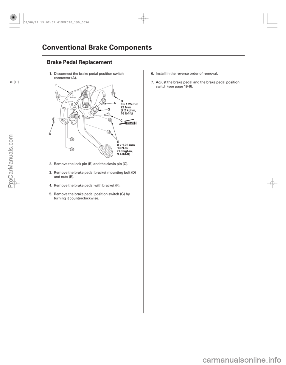
Brake Pedal Replacement
A
B CD
8x1.25mm
22 N·m
(2.2 kgf·m,
16 lbf·ft)
F
E
8x1.25mm
13 N·m
(1.3 kgf·m,
9.4 lbf·ft)
G
1. Disconnect the brake pedal position switch
connector (A).
2. Remove the lock pin (B) and the clevis pin (C).
3. Remove the brake pedal bracket mounting bolt (D) and nuts (E).
4. Remove the brake pedal with bracket (F).
5. Remove the brake pedal position switch (G) by turning it counterclockwise. 6. Install in the reverse order of removal.
7. Adjust the brake pedal and the brake pedal position
switch (see page 19-6).
08/08/21 15:02:07 61SNR030_190_0036
ProCarManuals.com
DYNOMITE -2009-