Page 999 of 2893
����
�µ
�µ
�µ
�µ �µ
�µ
DTC P0705:
YES
NO
YES
NO YES
NO
14-83
ATPP (BLK/BLU)
GND (BLK)
TRANSMISSION RANGE
SWITCH CONNECTOR
Short in Transmiss")
����
�(�#�'�������
� �����
�����������������������)����
�µ
�µ
�µ
�µ �µ
�µ
DTC P0705:
YES
NO
YES
NO YES
NO
14-83
ATPP (BLK/BLU)
GND (BLK)
TRANSMISSION RANGE
SWITCH CONNECTOR
Short in Transmission Range
Switch Circuit (Multiple Shift-position Input)
NOTE:
Before you troubleshoot, record all freeze data and any on-board snapshot with the HDS, and review
General Troubleshooting Information (see page 14-3).
This code is caused by an electrical circuit problem and cannot be caused by a mechanical problem in the
transmission.
1. Turn the ignition switch to ON (II).
2. Clear the DTC with the HDS.
3. Start the engine.
4. With the brake pedal pressed, move the shift lever through all positions. Stop for at least 1 second in
each position.
5. Monitor the OBD STATUS for P0705 in the DTCs MENU with the HDS.
Go to step 6.
If the HDS indicates PASSED, intermittent
failure, the system is OK at this time. Check for
intermittent short to body ground in the wires
between the transmission range switch and the
PCM. If the HDS indicates NOT COMPLETED, go to
step 3.
6. Turn the ignition switch to LOCK (0).
7. Inspect the transmission range switch (see page 14-265).
With the switch connector disconnected, go
to step 8.
Replace the transmission range switch
(see page 14-267), then go to step 45. 8. Turn the ignition switch to ON (II).
9. Measure the voltage between transmission range
switch connector terminals No. 6 and No. 10.
Go to step 15.
Go to step 10.
(cont’d)
Wire side of female terminals
Does the HDS ind icate F AILED?Is the switch OK ? I s t her e mor e t han 5 V ?
08/08/21 14:39:48 61SNR030_140_0085
ProCarManuals.com
DYNOMITE -2009-
Page 1000 of 2893

PCM CONNECTOR B (44P)
ATPP (BLU/BLK) TRANSMISSION RANGE
SWITCH CONNECTOR
GND (BLK)
10. Turn the ign")
���������
�µ
�µ �µ
�µ
YES
NO YES
NO
14-84Automatic Transmission
DTC Troubleshooting (cont’d)
PCM CONNECTOR B (44P)
ATPP (BLU/BLK) TRANSMISSION RANGE
SWITCH CONNECTOR
GND (BLK)
10. Turn the ignition switch to LOCK (0).
11. Jump the SCS line with the HDS.
12. Disconnect PCM connector B (44P).
13. Check for continuity between PCM connectorterminal B13 and body ground.
Repair short to body ground in the wire
between PCM connector terminal B13 and the
transmission range switch, then go to step 45.
Go to step 14. 14. Check for continuity between transmission range
switch connector terminal No. 10 and body ground.
Go to step 52.
Repair open in the wire between transmission
range switch connector terminal No. 10 and body
ground (G 101) (see page 22-16), or repair poor
body ground (G 101), then go to step 45.
Terminal side of female terminals Wire side of female terminals
Is there continuity?
Is there continuity?
08/08/21 14:39:48 61SNR030_140_0086
ProCarManuals.com
DYNOMITE -2009-
Page 1001 of 2893
����������
�µ
�µ �µ
�µ
YES
NO
YES
NO
14-85
ATPR (WHT)
GND (BLK)
TRANSMISSION RANGE
SWITCH CONNECTOR
PCM CONNECTOR B (44P)
ATPR (WHT)
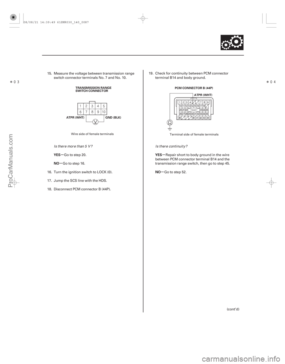
15. Measure the voltage between transmission rangeswitch connector terminals No. 7 and No. 10.
Go to step 20.
Go to step 16.
16. Turn the ignition switch to LOCK (0).
17. Jump the SCS line with the HDS.
18. Disconnect PCM connector B (44P). 19. Check for continuity between PCM connector
terminal B14 and body ground.
Repair short to body ground in the wire
between PCM connector terminal B14 and the
transmission range switch, then go to step 45.
Go to step 52.
(cont’d)
Wire side of female terminals Terminal side of female terminals
I s t her e mor e t han 5 V ?I s t her e cont i nui t y ?
08/08/21 14:39:49 61SNR030_140_0087
ProCarManuals.com
DYNOMITE -2009-
Page 1002 of 2893
����������
�µ
�µ �µ
�µ
YES
NO
YES
NO
14-86Automatic Transmission
DTC Troubleshooting (cont’d)
GND (BLK)
TRANSMISSION RANGE
SWITCH CONNECTOR
ATPN
(RED/BLK) PCM CONNECTOR B (44P)
ATPN (RED/BLK)
20. Measure the voltage between transmission rangeswitch connector terminals No. 2 and No. 10.
Go to step 25.
Go to step 21.
21. Turn the ignition switch to LOCK (0).
22. Jump the SCS line with the HDS.
23. Disconnect PCM connector B (44P). 24. Check for continuity between PCM connector
terminal B12 and body ground.
Repair short to body ground in the wire
between PCM connector terminal B12 and the
transmission range switch, then go to step 45.
Go to step 52.
Wire side of female terminals Terminal side of female terminals
I s t her e mor e t han 5 V ?I s t her e cont i nui t y ?
08/08/21 14:39:49 61SNR030_140_0088
ProCarManuals.com
DYNOMITE -2009-
Page 1003 of 2893
����������
�µ
�µ �µ
�µ
YES
NO
YES
NO
14-87
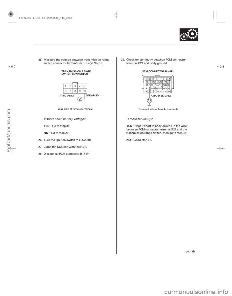
ATPD (PNK)TRANSMISSION RANGE
SWITCH CONNECTOR
GND (BLK) PCM CONNECTOR B (44P)
ATPD (YEL/GRN)
25. Measure the voltage between transmission rangeswitch connector terminals No. 8 and No. 10.
Go to step 30.
Go to step 26.
26. Turn the ignition switch to LOCK (0).
27. Jump the SCS line with the HDS.
28. Disconnect PCM connector B (44P). 29. Check for continuity between PCM connector
terminal B21 and body ground.
Repair short to body ground in the wire
between PCM connector terminal B21 and the
transmission range switch, then go to step 45.
Go to step 52.
(cont’d)
Wire side of female terminals Terminal side of female terminals
Is t her e about bat t er y v ol t age?Is t her e cont i nui t y ?
08/08/21 14:39:49 61SNR030_140_0089
ProCarManuals.com
DYNOMITE -2009-
Page 1004 of 2893
�������
��
�µ
�µ �µ
�µ
YES
NO
YES
NO
14-88Automatic Transmission
DTC Troubleshooting (cont’d)
ATPS (BLU)
GND (BLK)
TRANSMISSION RANGE
SWITCH CONNECTOR
PCM CONNECTOR B (44P)
ATPS (RED)
30. Measure the voltage between transmission range switch connector terminals No. 3 and No. 10.
Go to step 35.
Go to step 31.
31. Turn the ignition switch to LOCK (0).
32. Jump the SCS line with the HDS.
33. Disconnect PCM connector B (44P). 34. Check for continuity between PCM connector
terminal B15 and body ground.
Repair short to body ground in the wire
between PCM connector terminal B15 and the
transmission range switch, then go to step 45.
Go to step 52.
Wire side of female terminals Terminal side of female terminals
Is t her e about bat t er y v ol t age?Is t her e cont i nui t y ?
08/08/21 14:39:50 61SNR030_140_0090
ProCarManuals.com
DYNOMITE -2009-
Page 1005 of 2893
��
�
��
��
�µ
�µ �µ
�µ
YES
NO
YES
NO
14-89
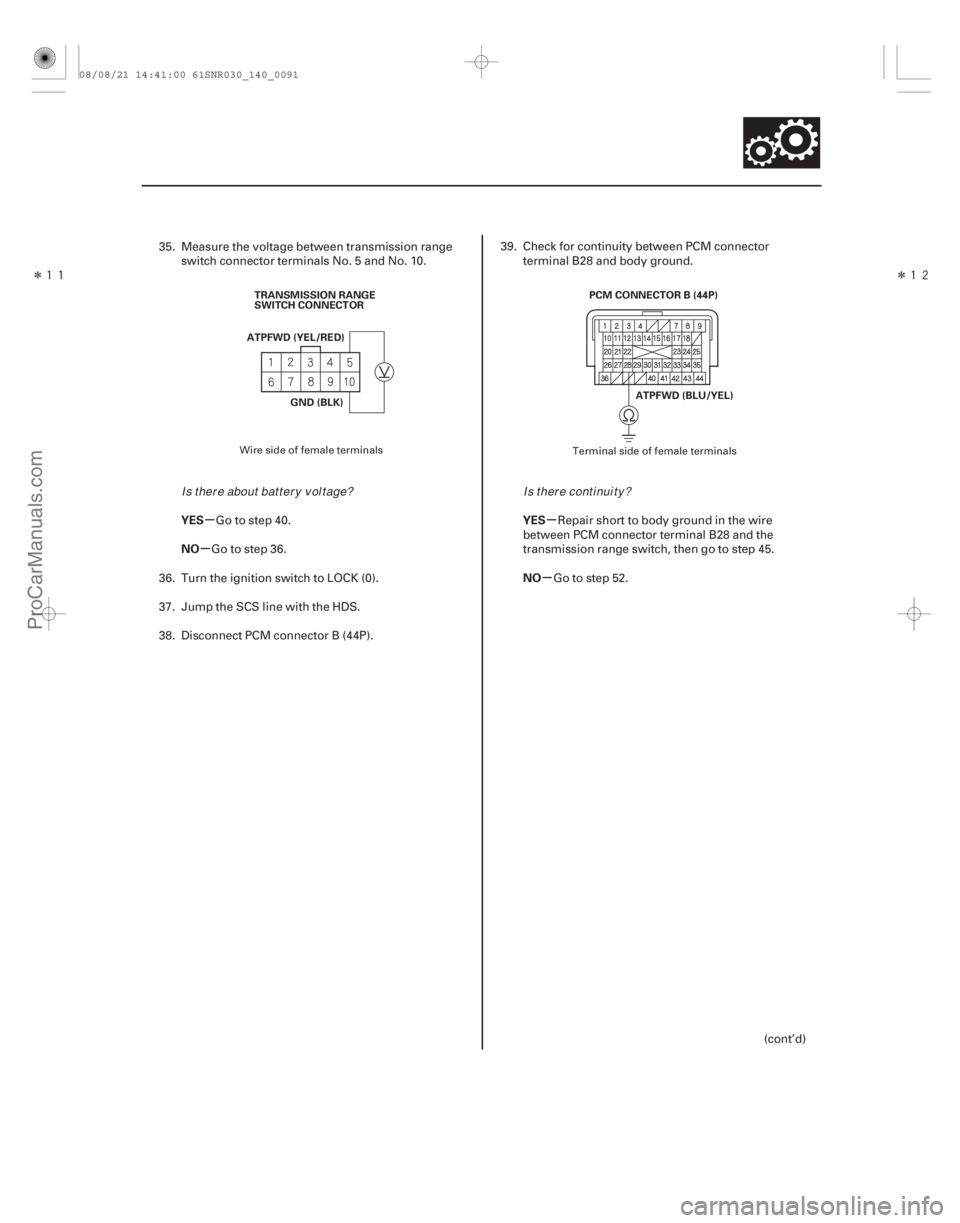
ATPFWD (YEL/RED)
GND (BLK)
TRANSMISSION RANGE
SWITCH CONNECTOR
PCM CONNECTOR B (44P)
ATPFWD (BLU/YEL)
35. Measure the voltage between transmission rangeswitch connector terminals No. 5 and No. 10.
Go to step 40.
Go to step 36.
36. Turn the ignition switch to LOCK (0).
37. Jump the SCS line with the HDS.
38. Disconnect PCM connector B (44P). 39. Check for continuity between PCM connector
terminal B28 and body ground.
Repair short to body ground in the wire
between PCM connector terminal B28 and the
transmission range switch, then go to step 45.
Go to step 52.
(cont’d)
Wire side of female terminals Terminal side of female terminals
Is t her e about bat t er y v ol t age?Is t her e cont i nui t y ?
08/08/21 14:41:00 61SNR030_140_0091
ProCarManuals.com
DYNOMITE -2009-
Page 1006 of 2893
��
����
��
�µ
�µ �µ
�µ
YES
NO
YES
NO
14-90Automatic Transmission
DTC Troubleshooting (cont’d)
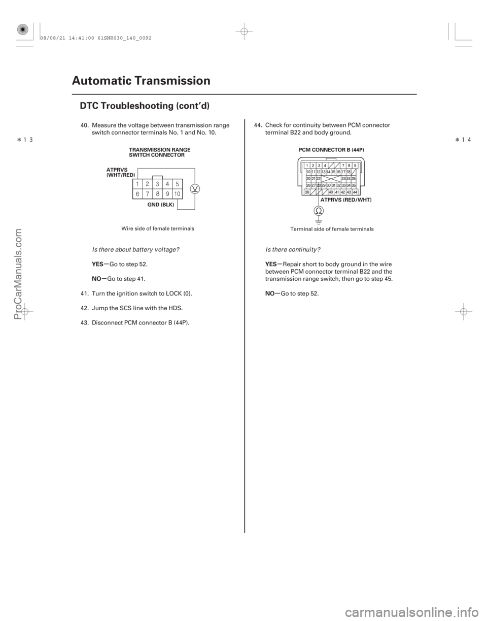
TRANSMISSION RANGE
SWITCH CONNECTOR
ATPRVS
(WHT/RED)
GND (BLK) PCM CONNECTOR B (44P)
ATPRVS (RED/WHT)
40. Measure the voltage between transmission rangeswitch connector terminals No. 1 and No. 10.
Go to step 52.
Go to step 41.
41. Turn the ignition switch to LOCK (0).
42. Jump the SCS line with the HDS.
43. Disconnect PCM connector B (44P). 44. Check for continuity between PCM connector
terminal B22 and body ground.
Repair short to body ground in the wire
between PCM connector terminal B22 and the
transmission range switch, then go to step 45.
Go to step 52.
Wire side of female terminals Terminal side of female terminals
Is t her e about bat t er y v ol t age?Is t her e cont i nui t y ?
08/08/21 14:41:00 61SNR030_140_0092
ProCarManuals.com
DYNOMITE -2009-