���
�(�#�'�������������������������������
� �����)���� ���
����
�(�#�'�������������������������������
� �����)���� Washer reservoir capacity: 4.5 L (4.8 US qt)
22-23422-234
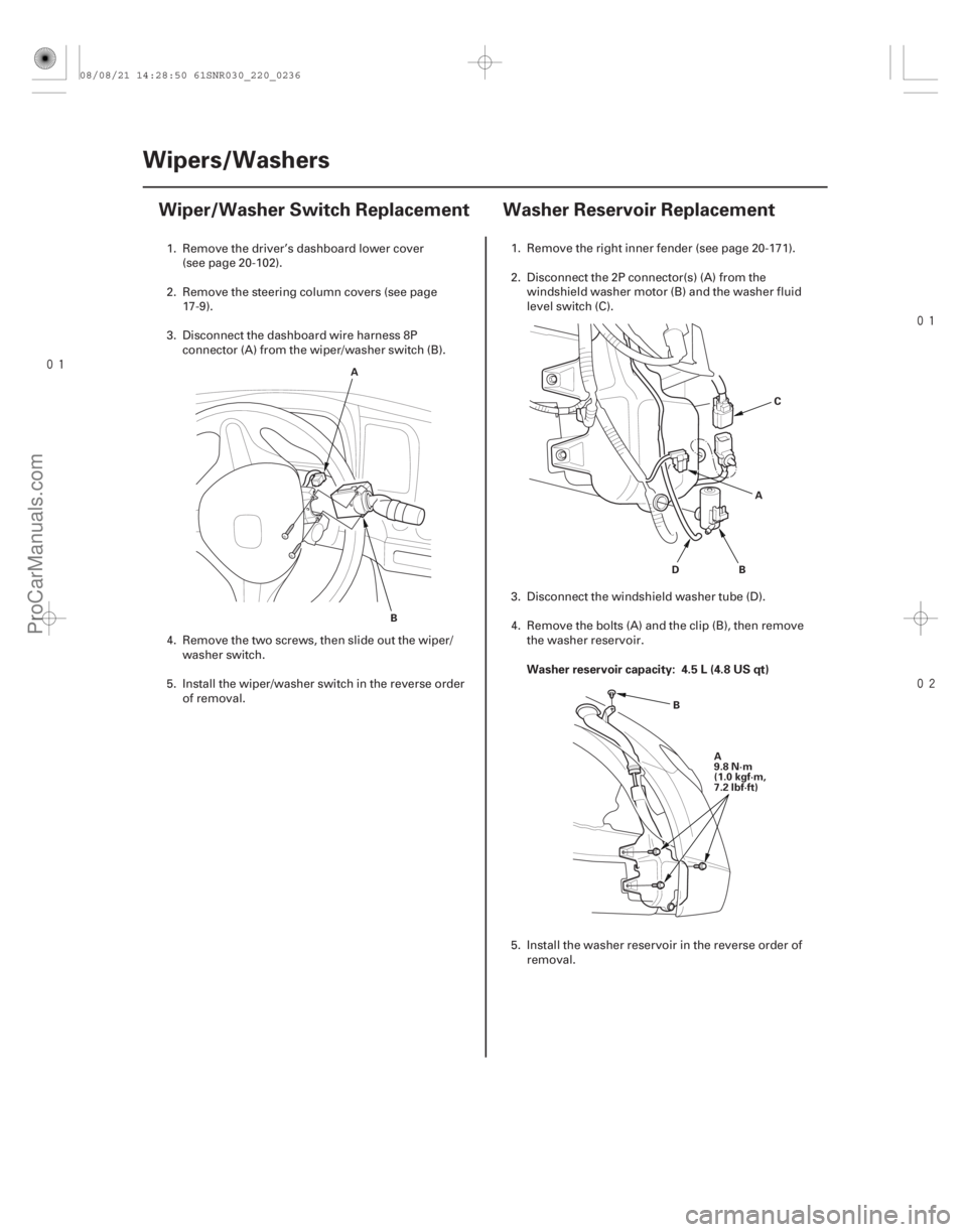
Wipers/Washers
Wiper/Washer Switch Replacement Washer Reservoir Replacement
A
B B
D AC
A
9.8 N·m
(1.0 kgf·m,
7.2 lbf·ft)
B
1. Remove the driver’s dashboard lower cover
(see page 20-102).
2. Remove the steering column covers (see page 17-9).
3. Disconnect the dashboard wire harness 8P connector (A) from the wiper/washer switch (B).
4. Remove the two screws, then slide out the wiper/ washer switch.
5. Install the wiper/washer switch in the reverse order of removal. 1. Remove the right inner fender (see page 20-171).
2. Disconnect the 2P connector(s) (A) from the
windshield washer motor (B) and the washer fluid
level switch (C).
3. Disconnect the windshield washer tube (D).
4. Remove the bolts (A) and the clip (B), then remove the washer reservoir.
5. Install the washer reservoir in the reverse order of removal.
08/08/21 14:28:50 61SNR030_220_0236
ProCarManuals.com
DYNOMITE -2009-
�¦�§
�¦�§
���
�(�#�'�������������������������������
�"�����)���� Wiper arms stop position
Washer nozzle position
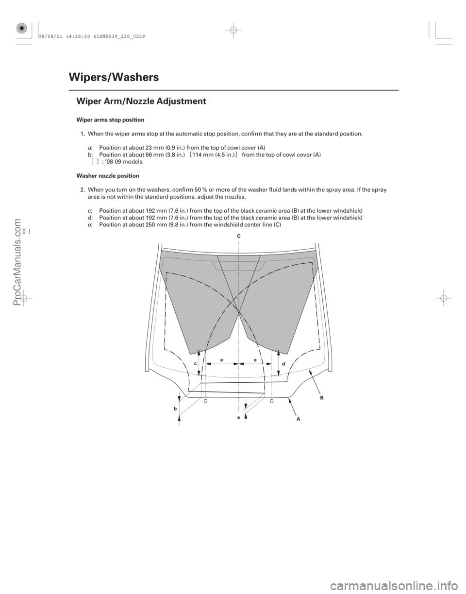
22-236Wipers/Washers
Wiper Arm/Nozzle Adjustment
C
B
A
d
e
b a
c
e
1. When the wiper arms stop at the automatic stop position, confirm that they are at the standard position.
a: Position at about 23 mm (0.9 in.) from the top of cowl cover (A)
b: Position at about 96 mm (3.8 in.) 114 mm (4.5 in.) from the top of cowl cover (A) : ’08-09 models
2. When you turn on the washers, confirm 50 % or more of the washer fluid lands within the spray area. If the spray area is not within the standard positions, adjust the nozzles.
c: Position at about 192 mm (7.6 in.) from the top of the black ceramic area (B) at the lower windshield
d: Position at about 192 mm (7.6 in.) from the top of the black ceramic area (B) at the lower windshield
e: Position at about 250 mm (9.8 in.) from the windshield center line (C)
08/08/21 14:28:50 61SNR030_220_0238
ProCarManuals.com
DYNOMITE -2009-
�´�µ
���
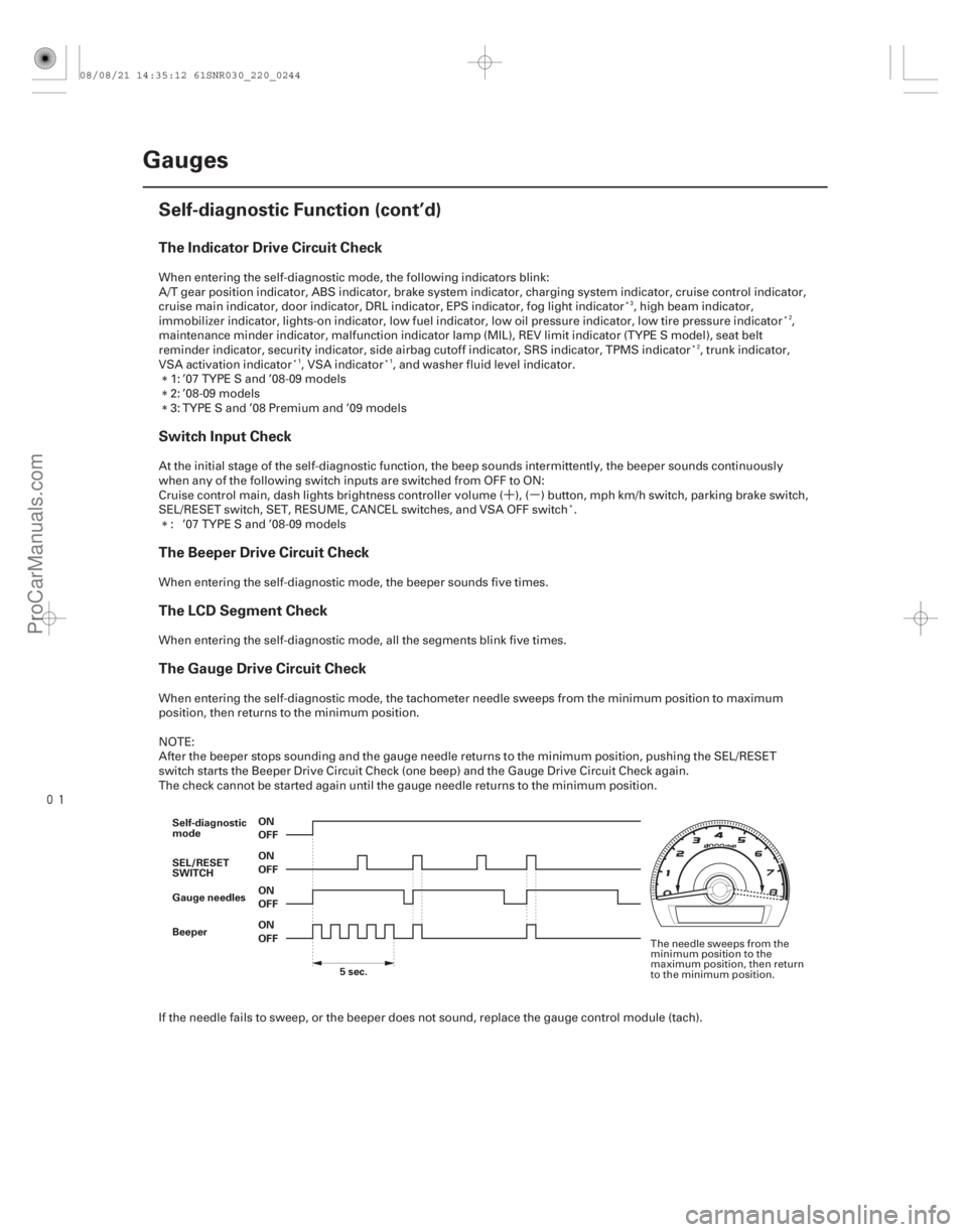
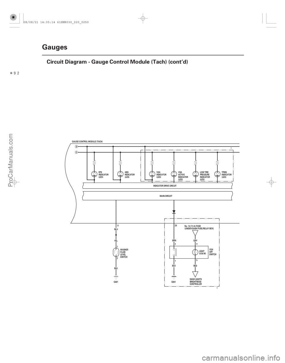
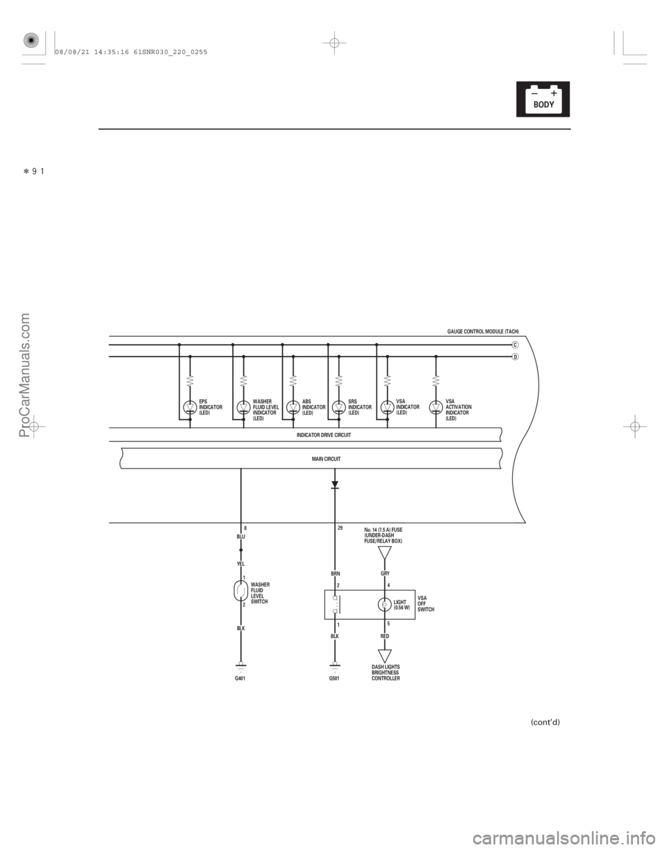
The Indicator Drive Circuit Check
Switch Input Check
The Beeper Drive Circuit Check
The LCD Segment Check
The Gauge Drive Circuit Check
22-242Gauges
Self-diagnostic Function (cont’d)
OFF ON
OFF ON
OFF ON
OFF ON
Gauge needles
Beeper
5sec.
Self-diagnostic
mode
SEL/RESET
SWITCH
When entering the self-diagnostic mode, the following indicators blink:
A/T gear position indicator, ABS indicator, brake system indicator, charging system indicator, cruise control indicator,
cruise main indicator, door indicator, DRL indicator, EPS indicator, fog light indicator , high beam indicator,
immobilizer indicator, lights-on indicator, low fuel indicator, low oil pressure indicator, low tire pressure indicator ,
maintenance minder indicator, malfunction indicator lamp (MIL), REV limit indicator (TYPE S model), seat belt
reminder indicator, security indicator, side airbag cutoff indicator, SRS indicator, TPMS indicator , trunk indicator,
VSA activation indicator , VSA indicator , and washer fluid level indicator.
1: ’07 TYPE S and ’08-09 models
2: ’08-09 models
3: TYPE S and ’08 Premium and ’09 models
At the initial stage of the self-diagnostic function, the beep sounds intermittently, the beeper sounds continuously
when any of the following switch inputs are switched from OFF to ON:
Cruise control main, dash lights brightness controller volume ( ), ( ) button, mph km/h switch, parking brake switch,
SEL/RESET switch, SET, RESUME, CANCEL switches, and VSA OFF switch . : ’07 TYPE S and ’08-09 models
When entering the self-diagnostic mode, the beeper sounds five times.
When entering the self-diagnostic mode, all the segments blink five times.
When entering the self-diagnostic mode, the tachometer needle sweeps from the minimum position to maximum
position, then returns to the minimum position.
NOTE:
After the beeper stops sounding and the gauge needle returns to the minimum position, pushing the SEL/RESET
switch starts the Beeper Drive Circuit Check (one beep) and the Gauge Drive Circuit Check again.
The check cannot be started again until the gauge needle returns to the minimum position.
If the needle fails to sweep, or the beeper does not sound, replace the gauge control module (tach).
3 2
2
11
The needle sweeps from the
minimum position to the
maximum position, then return
to the minimum position.
08/08/21 14:35:12 61SNR030_220_0244
ProCarManuals.com
DYNOMITE -2009-
�´
�´
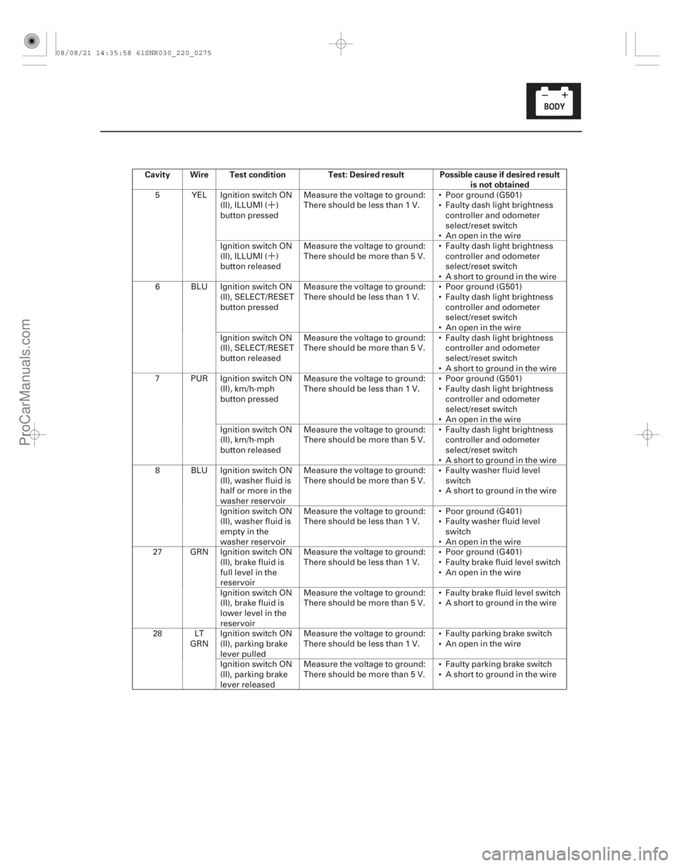
Cavity Wire Test condition Test: Desired result Possible cause if desired result
is not obtained
22-273
5 YEL Ignition switch ON
(II), ILLUMI ( )
button pressed Measure the voltage to ground:
There should be less than 1 V.
Poor ground (G501)
Faulty dash light brightness
controller and odometer
select/reset switch
An open in the wire
Ignition switch ON
(II), ILLUMI ( )
button released Measure the voltage to ground:
There should be more than 5 V.
Faulty dash light brightness
controller and odometer
select/reset switch
A short to ground in the wire
6 BLU Ignition switch ON (II), SELECT/RESET
button pressed Measure the voltage to ground:
There should be less than 1 V.
Poor ground (G501)
Faulty dash light brightness
controller and odometer
select/reset switch
An open in the wire
Ignition switch ON
(II), SELECT/RESET
button released Measure the voltage to ground:
There should be more than 5 V.
Faulty dash light brightness
controller and odometer
select/reset switch
A short to ground in the wire
7 PUR Ignition switch ON (II), km/h-mph
button pressed Measure the voltage to ground:
There should be less than 1 V.
Poor ground (G501)
Faulty dash light brightness
controller and odometer
select/reset switch
An open in the wire
Ignition switch ON
(II), km/h-mph
button released Measure the voltage to ground:
There should be more than 5 V.
Faulty dash light brightness
controller and odometer
select/reset switch
A short to ground in the wire
8 BLU Ignition switch ON (II), washer fluid is
half or more in the
washer reservoir Measure the voltage to ground:
There should be more than 5 V.
Faulty washer fluid level
switch
A short to ground in the wire
Ignition switch ON
(II), washer fluid is
empty in the
washer reservoir Measure the voltage to ground:
There should be less than 1 V.
Poor ground (G401)
Faulty washer fluid level
switch
An open in the wire
27 GRN Ignition switch ON (II), brake fluid is
full level in the
reservoir Measure the voltage to ground:
There should be less than 1 V.
Poor ground (G401)
Faulty brake fluid level switch
An open in the wire
Ignition switch ON
(II), brake fluid is
lower level in the
reservoir Measure the voltage to ground:
There should be more than 5 V.
Faulty brake fluid level switch
A short to ground in the wire
28 LT GRNIgnition switch ON
(II), parking brake
lever pulled Measure the voltage to ground:
There should be less than 1 V.
Faulty parking brake switch
An open in the wire
Ignition switch ON
(II), parking brake
lever released Measure the voltage to ground:
There should be more than 5 V.
Faulty parking brake switch
A short to ground in the wire
08/08/21 14:35:58 61SNR030_220_0275
ProCarManuals.com
DYNOMITE -2009-