Page 1328 of 2893
����
�(�#�'���������������������������
���
�"�����)����
17-5
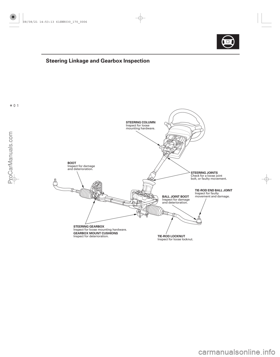
Steering Linkage and Gearbox Inspection
STEERING COLUMN STEERING JOINTSTIE-ROD END BALL JOINT
BALL JOINT BOOT
BOOT
STEERING GEARBOX
GEARBOX MOUNT CUSHIONS TIE-ROD LOCKNUT
Inspect for loose
mounting hardware.
Check for a loose joint
bolt, or faulty movement.Inspect for faulty
movement and damage.
Inspect for damage
and deterioration.
Inspect for damage
and deterioration.
Inspect for loose mounting hardware.
Inspect for deterioration. Inspect for loose locknut.
08/08/21 14:53:13 61SNR030_170_0006
ProCarManuals.com
DYNOMITE -2009-
Page 1338 of 2893
���
Special Tools Required
17-16
Steering
Tie-rod End Ball Joint Boot Replacement
C
D
D
A
B
E A
B
07JAF-SH20330
Bushing base 07JAF-SH20330
1. Di")
���
����
�(�#�'�������������������������������
� �����)���
Special Tools Required
17-16
Steering
Tie-rod End Ball Joint Boot Replacement
C
D
D
A
B
E A
B
07JAF-SH20330
Bushing base 07JAF-SH20330
1. Disconnect the tie-rod end ball joint from the knuckle (see step 17 on page 17-67).
2. Remove the tie-rod end from the rack end.
3. Remove the tie-rod ball joint boot from the tie-rod end, and wipe the old grease off the ball pin.
4. Pack the lower area of the ball pin (A) with fresh multipurpose grease.
5. Pack the interior of the new tie-rod end ball joint boot (B) and lip (C) with fresh multipurpose grease.
Note these items when installing new grease: Keep grease off the boot mounting area (D) and the tapered section (E) of the ball pin.
Do not allow dust, dirt, or other foreign materials to enter the boot. 6. Install the new tie-rod end ball joint boot (A) using
the bushing base. The boot must not have a gap at
the boot installation sections (B). After insta lling the
boot, check the ball pin tapered section for grease
contamination, and wipe it if necessary.
7. Install the tie-rod end to the rack end.
8. Connect the tie-rod end ball joint to the knuckle (see step 25 on page 17-76).
9. Check the wheel alignment, and adjust it if necessary (see page 18-5).
08/08/21 14:53:19 61SNR030_170_0017
ProCarManuals.com
DYNOMITE -2009-
Page 1402 of 2893
����
�(�#�'�����������
���
�����������
����� �����)����
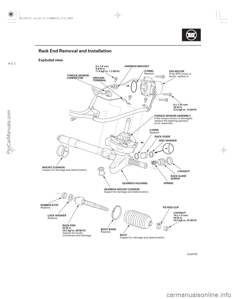
Exploded view
17-79
Rack End Removal and Installation
O-RING
TORQUE SENSOR
CONNECTOR
8x1.25mm
20 N·m
(2.0 kgf·m, 14 lbf·ft)
EPS MOTOR
6x1.0mm
9.8 N·m
(1.0 kgf·m, 7.2 lbf·ft)
LOCKNUT
RACK GUIDE
DISC WASHER
O-RING
SPRING
GEARBOX MOUNT CUSHION GEARBOX HOUSING
MOUNT CUSHION
TIE-ROD CLIPLOCKNUT
14 x 1.5 mm
44 N·m
(4.5 kgf·m, 33 lbf·ft)
BOOT
BOOT BAND
RACK END
93 N·m
(9.5 kgf·m, 69 lbf·ft)
LOCK WASHER
RUBBER STOP GROUND
TERMINAL
TORQUE SENSOR ASSEMBLY
RACK GUIDE
SCREW
HARNESS BRACKET
(cont’d)
Replace.
If the EPS motor is
faulty, replace it.
Replace.
Inspect for damage and deterioration.
Inspect for damage and deterioration.
Inspect for damage and deterioration.
Replace.
Inspect for faulty
movement and damage.
Replace.
Replace. If the torque sensor is damaged,
replace the steering gearbox
as an assembly.
08/08/21 14:55:19 61SNR030_170_0080
ProCarManuals.com
DYNOMITE -2009-
Page 1403 of 2893
��������
����
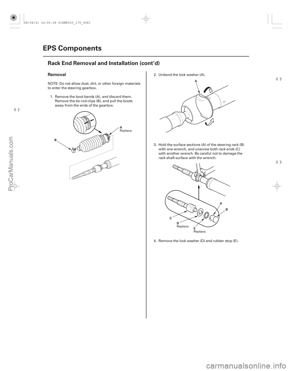
Removal
17-80EPS Components
Rack End Removal and Installation (cont’d)
B
A A
E
D A
B
C
NOTE: Do not allow dust, dirt, or other foreign materials
to enter the steering gearbox. 1. Remove the boot bands (A), and discard them. Remove the tie-rod clips (B), and pull the boots
away from the ends of the gearbox. 2. Unbend the lock washer (A).
3. Hold the surface sections (A) of the steering rack (B)
with one wrench, and unscrew both rack ends (C)
with another wrench. Be careful not to damage the
rack shaft surface with the wrench.
4. Remove the lock washer (D) and rubber stop (E).
Replace.
Replace.
Replace.
08/08/21 14:55:28 61SNR030_170_0081
ProCarManuals.com
DYNOMITE -2009-
Page 1404 of 2893

A
B A
B
(P/N 08798-9013)
1. Install a new rubber stop (A) and a new lock washer (B). Align the lock washer tabs (C) with the")
����
��������
Installation
17-81
A
B C
D
E
93 N·m
(9.5 kgf·m,
69 lbf·ft)
A
B A
B
(P/N 08798-9013)
1. Install a new rubber stop (A) and a new lock washer (B). Align the lock washer tabs (C) with the slots (D)
on the rack end (E) while holding the lock washer in
place. Repeat this step for the other side of the rack
shaft.
2. Hold the flat surface sections of the steering rack with one wrench, and tighten both rack ends with
another wrench. Be careful not to damage the rack
surface with the wrench.
3. Bend the lock washer (A) back against the flat spots (B) on the rack end ball joint housing. 4. Apply multipurpose grease to the circumference of
the rack end joint housing (A) and lock washer.
5. Apply a light coat of silicone grease (P/N 08798-9013) to the boot fitting grooves (B) on the
rack ends.
NOTE: Make sure not to get any silicone grease on
the terminal part of the connectors and switches,
especially if you have silicone grease on your
hands or gloves.
(cont’d)
Replace.
Replace.
08/08/21 14:55:28 61SNR030_170_0082
ProCarManuals.com
DYNOMITE -2009-
Page 1405 of 2893
��������
����
17-82EPS Components
Rack End Removal and Installation (cont’d)
A
B
C
D A
B
BA4mm
(0.16 in.)
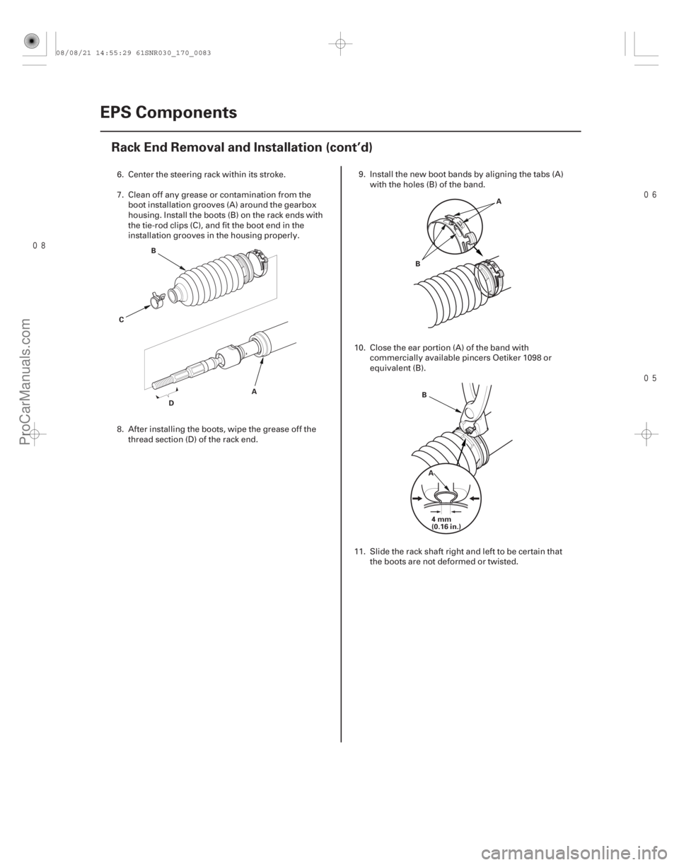
6. Center the steering rack within its stroke.
7. Clean off any grease or contamination from the boot installation grooves (A) around the gearbox
housing. Install the boots (B) on the rack ends with
the tie-rod clips (C), and fit the boot end in the
installation grooves in the housing properly.
8. After installing the boots, wipe the grease off the
thread section (D) of the rack end. 9. Install the new boot bands by aligning the tabs (A)
with the holes (B) of the band.
10. Close the ear portion (A) of the band with commercially available pincers Oetiker 1098 or
equivalent (B).
11. Slide the rack shaft right and left to be certain that the boots are not deformed or twisted.
08/08/21 14:55:29 61SNR030_170_0083
ProCarManuals.com
DYNOMITE -2009-
Page 1408 of 2893
����
Suspension
Front and Rear Suspension
Front Suspension
Rear Suspension............................................. ..................................")
�(�#�'�������������������������
�����
�/�����)����
Suspension
Front and Rear Suspension
Front Suspension
Rear Suspension............................................. .............................................
TPMS (Tire Pressure Monitoring System)
(’08-09 Models) . 18-47
................................................................
........................................
......................................................... ...........................
...........................................
............................................
...................................................... ...................
Special Tools . 18-2
Component Location Index . 18-3
Wheel Alignment . 18-5
Wheel Bearing End Play Inspection . 18-9
Wheel Runout Inspection . 18-9
Wheel Bolt Replacement . 18-10
Ball Joint Removal . 18-12
Ball Joint Boot Inspection/Replacement . 18-13
...............
................................... ............................... ..........................
........................................ .................
................................... ...............
................................... ............................... ..........................
........................................ .................
...................................
Knuckle/Hub/Wheel Bearing Replacement . 18-14
Lower Ball Joint Replacement
. 18-20
Lower Arm Removal/Installation . 18-22
Stabilizer Link Removal/Installation . 18-25
Stabilizer Bar Replacement . 18-25
Damper/Spring Removal and Installation . 18-26
Damper/Spring Disassembly, Inspection, and Reassembly . 18-28
...................
............................... ............................. ..........................
........................................
.................................................
.................................................... ...................
............................... ............................. ..........................
........................................
.................................................
....................................................
Knuckle/Hub Bearing Unit Replacement
. 18-31
Upper Arm Removal/Installation . 18-35
Trailing Arm Removal/Installation . 18-36
Stabilizer Link Removal/Installation . 18-37
Stabilizer Bar Replacement . 18-38
Damper Replacement . 18-39
Spring Replacement . 18-42
08/08/21 14:56:38 61SNR030_180_0001
ProCarManuals.com
DYNOMITE -2009-
Page 1410 of 2893
����
�(�#�'���������������������������������������)���� Front Suspension
18-3
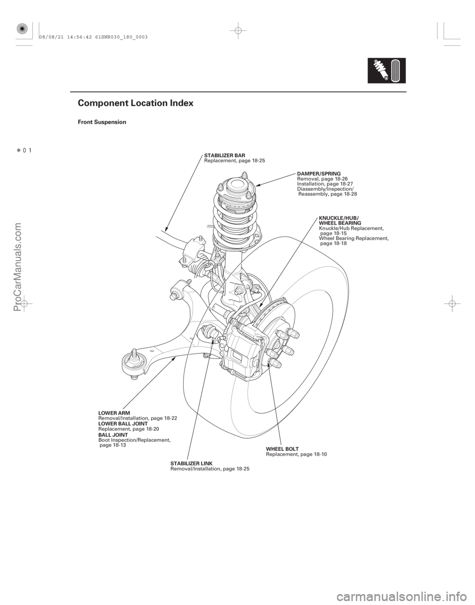
Component Location Index
STABILIZER BAR
LOWER ARM STABILIZER LINK KNUCKLE/HUB/
WHEEL BEARING
DAMPER/SPRING
WHEEL BOLT
BALL JOINT LOWER BALL JOINT Replacement, page 18-25
Removal/Installation, page 18-22 Removal/Installation, page 18-25 Knuckle/Hub Replacement,
page 18-15
Wheel Bearing Replacement,
page 18-18
Removal, page 18-26
Installation, page 18-27
Diassembly/Inspection/
Reassembly, page 18-28
Replacement, page 18-10
Boot Inspection/Replacement,
page 18-13
Replacement, page 18-20
08/08/21 14:56:42 61SNR030_180_0003
ProCarManuals.com
DYNOMITE -2009-