Page 1296 of 2893
���
���
����
�(�#������������
��������������������� �����)����
16-416-4 Driveline/Axle
Driveshaft Inspection
Driveshaft Removal
F
D B
C
A
E A
B
1.")
���
�(�#�'�����������
���������������������"�����)���
���
����
�(�#�'�����������
��������������������� �����)����
16-416-4 Driveline/Axle
Driveshaft Inspection
Driveshaft Removal
F
D B
C
A
E A
B
1. Check the inboard boot (A) and the outboard boot (B) on the driveshaft (C) for cracks, damage, leaking
grease, and loose boot bands (D). If any damage is
found, replace the boot and the boot bands.
2. Check the driveshaft for cracks and damage. If any damage is found, replace the driveshaft.
3. Check the inboard joint (E) and the outboard joint (F) for cracks and damage. If any damage is found,
replace the inboard joint or the outboard joint as an
assembly.
4. Hold the inboard joint and turn the front wheel by hand, then make sure the joint is not excessively
loose. If necessary, replace the inboard joint or the
outboard joint as an assembly. 1. Raise the vehicle on a lift.
2. Remove the front wheels.
3. Pry up the locking tab (A) on the spindle nut (B),
then remove the nut.
4. Drain the transmission fluid, then reinstall the drain plug with a new sealing washer:
5-speed manual transmission (see page 13-5)
6-speed manual transmission (see page 13-82)
Automatic transmission (see page 14-232)
5. Remove the nuts and the bolt, then separate the lower arm using a prybar.
08/08/21 14:51:21 61SNR030_160_0004
ProCarManuals.com
DYNOMITE -2009-
Page 1298 of 2893
����
��������
�(�#�'�����������
���������������������!�����)���� Special Tools Required Welded type
Inboard Joint Side
16-616-6Driveline/Axle
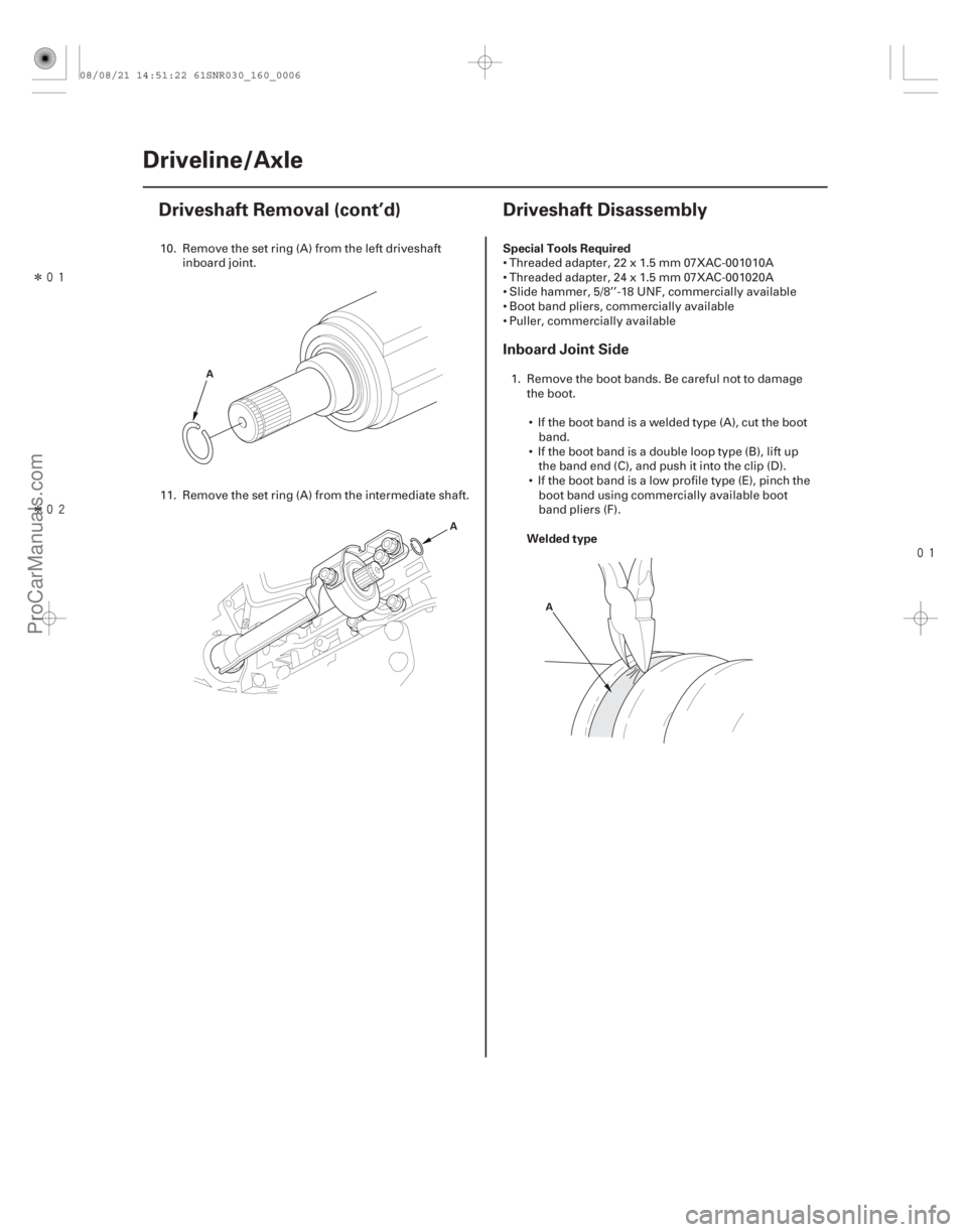
Driveshaft Removal (cont’d)
Driveshaft Disassembly
A
AA
10. Remove the set ring (A) from the left driveshaftinboard joint.
11. Remove the set ring (A) from the intermediate shaft. Threaded adapter, 22 x 1.5 mm 07XAC-001010A
Threaded adapter, 24 x 1.5 mm 07XAC-001020A
Slide hammer, 5/8’’-18 UNF, commercially available
Boot band pliers, commercially available
Puller, commercially available
1. Remove the boot bands. Be careful not to damage the boot.
If the boot band is a welded type (A), cut the boot band.
If the boot band is a double loop type (B), lift up the band end (C), and push it into the clip (D).
If the boot band is a low profile type (E), pinch the boot band using commercially available boot
band pliers (F).
08/08/21 14:51:22 61SNR030_160_0006
ProCarManuals.com
DYNOMITE -2009-
Page 1299 of 2893
����
��������
�(�#�'�����������
���������������������!�����)���� Special Tools Required Welded type
Inboard Joint Side
16-616-6Driveline/Axle
Driveshaft Removal (cont’d)
Driveshaft Disassembly
A
AA
10. Remove the set ring (A) from the left driveshaftinboard joint.
11. Remove the set ring (A) from the intermediate shaft. Threaded adapter, 22 x 1.5 mm 07XAC-001010A
Threaded adapter, 24 x 1.5 mm 07XAC-001020A
Slide hammer, 5/8’’-18 UNF, commercially available
Boot band pliers, commercially available
Puller, commercially available
1. Remove the boot bands. Be careful not to damage the boot.
If the boot band is a welded type (A), cut the boot band.
If the boot band is a double loop type (B), lift up the band end (C), and push it into the clip (D).
If the boot band is a low profile type (E), pinch the boot band using commercially available boot
band pliers (F).
08/08/21 14:51:22 61SNR030_160_0006
ProCarManuals.com
DYNOMITE -2009-
Page 1301 of 2893
��������
����
Outboard Joint Side
16-8Driveline/Axle
Driveshaft Disassembly (cont’d)
A
A
B
A
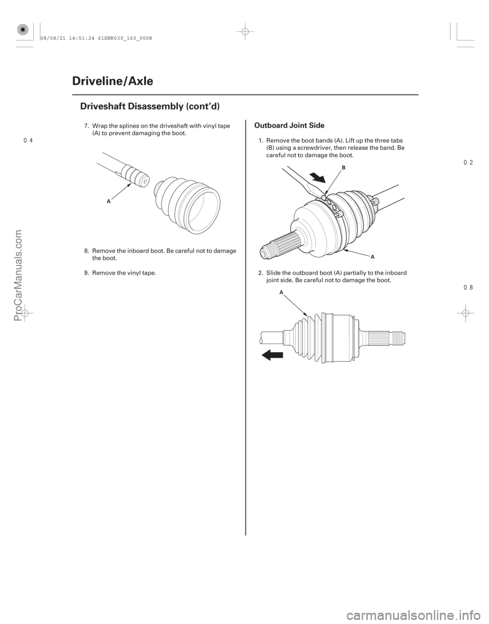
7. Wrap the splines on the driveshaft with vinyl tape (A) to prevent damaging the boot.
8. Remove the inboard boot. Be careful not to damage the boot.
9. Remove the vinyl tape. 1. Remove the boot bands (A). Lift up the three tabs
(B) using a screwdriver, then release the band. Be
careful not to damage the boot.
2. Slide the outboard boot (A) partially to the inboard joint side. Be careful not to damage the boot.
08/08/21 14:51:24 61SNR030_160_0008
ProCarManuals.com
DYNOMITE -2009-
Page 1302 of 2893
����
����� �
�
�
��
16-9
A
B
C
B
K20Z2 engine model: 22 x 1.5 mm 07XAC-001010A
K20Z3 engine model: 24 x 1.5 mm 07XAC-001020A AC A
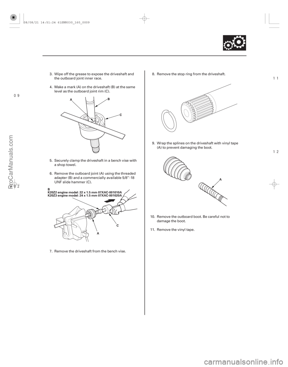
3. Wipe off the grease to expose the driveshaft and
the outboard joint inner race.
4. Make a mark (A) on the driveshaft (B) at the same level as the outboard joint rim (C).
5. Securely clamp the driveshaft in a bench vise with a shop towel.
6. Remove the outboard joint (A) using the threaded adapter (B) and a commercially available 5/8’’-18
UNF slide hammer (C).
7. Remove the driveshaft from the bench vise. 8. Remove the stop ring from the driveshaft.
9. Wrap the splines on the driveshaft with vinyl tape
(A) to prevent damaging the boot.
10. Remove the outboard boot. Be careful not to damage the boot.
11. Remove the vinyl tape.
08/08/21 14:51:24 61SNR030_160_0009
ProCarManuals.com
DYNOMITE -2009-
Page 1304 of 2893
����
�(�#�'�����������
���������������������!�����)����
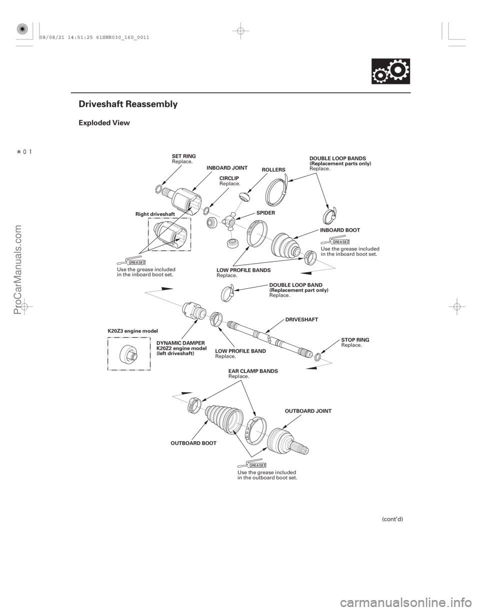
Exploded View
16-11
Driveshaft Reassembly
SET RINGINBOARD JOINT ROLLERS
SPIDER DOUBLE LOOP BANDS
(Replacement parts only)
INBOARD BOOT
LOW PROFILE BANDS DOUBLE LOOP BAND
(Replacement part only)
DRIVESHAFT STOP RING
LOW PROFILE BAND
DYNAMIC DAMPER
K20Z2 engine model
(left driveshaft)
OUTBOARD BOOT OUTBOARD JOINT
EAR CLAMP BANDS
CIRCLIP
Right driveshaft
K20Z3 engine model
(cont’d)
Replace. Replace.
Use the grease included
in the inboard boot set.
Replace.
Use the grease included
in the inboard boot set.
Replace.
Replace.
Replace.
Replace.
Use the grease included
in the outboard boot set.
Replace.
08/08/21 14:51:25 61SNR030_160_0011
ProCarManuals.com
DYNOMITE -2009-
Page 1305 of 2893

A
A
B
C
B
D B
C
A
Boot band tool, KD-3191 or equivalent commerciallyavailable
Boot")
��������
�����
Special Tools Required
Inboard Joint Side
16-12 Driveline/Axle
Driveshaft Reassembly (cont’d)
A
A
B
C
B
D B
C
A
Boot band tool, KD-3191 or equivalent commerciallyavailable
Boot band pliers, Kent-Moore J-35910 or equivalent, commercially available
NOTE: Refer to the Exploded View, as needed, during
this procedure.
1. Wrap the splines with vinyl tape (A) to prevent damaging the inboard boot.
2. Install the inboard boot onto the driveshaft, then remove the vinyl tape. Be careful not to damage the
inboard boot. 3. Install the spider (A) onto the driveshaft by aligning
the marks (B) you made on the spider and the end
of the driveshaft.
4. Install a new circlip (C) into the driveshaft groove. Always rotate the circlip in its groove to make sure
it is fully seated.
5. Fit the rollers (A) onto the spider (B) with their high shoulders (C) facing outward, and note these items:
Reinstall the rollers in their original positions on the spider by aligning the marks (D) you made.
Hold the driveshaft pointed up to prevent the rollers from falling off.
Replace.
08/08/21 14:51:26 61SNR030_160_0012
ProCarManuals.com
DYNOMITE -2009-
Page 1306 of 2893
����
��������
�µ �µ
�µ �µ
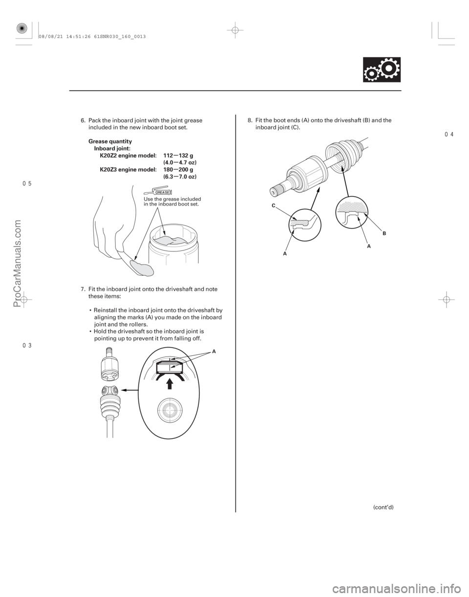
Grease quantity
Inboard joint:K20Z2 engine model: 112 132 g (4.0 4.7 oz)
K20Z3 engine model: 180 200 g (6.3 7.0 oz)
16-13
A A
B
C
A
6. Pack the inboard joint with the joint greaseincluded in the new inboard boot set.
7. Fit the inboard joint onto the driveshaft and note these items:
Reinstall the inboard joint onto the driveshaft by aligning the marks (A) you made on the inboard
joint and the rollers.
Hold the driveshaft so the inboard joint is pointing up to prevent it from falling off. 8. Fit the boot ends (A) onto the driveshaft (B) and the
inboard joint (C).
(cont’d)
Use the grease included
in the inboard boot set.
08/08/21 14:51:26 61SNR030_160_0013
ProCarManuals.com
DYNOMITE -2009-