Page 783 of 2893
�
��
����
���������
����
13-12Manual Transmission
Transmission Removal (cont’d)
A
A
BB
A B
C VSB02C000016
A
AB
A
A
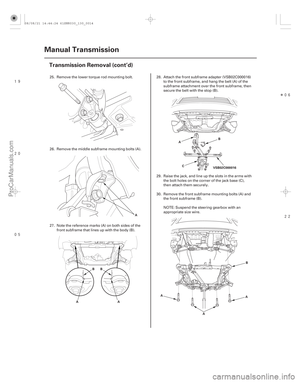
25. Remove the lower torque rod mounting bolt.
26. Remove the middle subframe mounting bolts (A).
27. Note the reference marks (A) on both sides of the
front subframe that lines up with the body (B). 28. Attach the front subframe adapter (VSB02C000016)
to the front subframe, and hang the belt (A) of the
subframe attachment over the front subframe, then
secure the belt with the stop (B).
29. Raise the jack, and line up the slots in the arms with the bolt holes on the corner of the jack base (C),
then attach them securely.
30. Remove the front subframe mounting bolts (A) and the front subframe (B).
NOTE: Suspend the steering gearbox with an
appropriate size wire.
08/08/21 14:44:24 61SNR030_130_0014
ProCarManuals.com
DYNOMITE -2009-
Page 788 of 2893

�
��
�
�������
�����
13-17
A
B 10x1.25mm
54 N·m
(5.5 kgf·m,
40 lbf·ft)
10x1.25mm
59 N·m (6.0 kgf·m, 43 lbf·ft)
A B
C
10x1.25mm
59 N·m
(6.0 kgf·m, 43 lbf·ft)
10x1.25mm
54 N·m
(5.5 kgf·m,
40 lbf·ft)10 x 1.25 mm
38 N·m
(3.9 kgf·m,
28 lbf·ft) 12x1.25mm
74 N·m
(7.5 kgf·m,
55 lbf·ft)
6x1.0mm
9.8 N·m
(1.0 kgf·m,
7.2 lbf·ft)
12x1.25mm
74 N·m
(7.5 kgf·m,
55 lbf·ft)
12x1.25mm
74 N·m
(7.5 kgf·m, 55 lbf·ft) B
A
A
14x1.5mm
93 N·m
(9.5 kgf·m,
69 lbf·ft)
16. Install the steering gearbox stiffener plate (A) andthe harness clip (B).
17. Install the stiffener plate (A) and the mounting bracket (B). Connect the exhaust mounting rubber
(C).
18. Connect the lower ball joint and the lower arm (see step 8 on page 16-21).
19. Lower the vehicle on the lift. 20. Install the transmission mount bracket (A), and
connect the ground cable (B).
21. Raise the vehicle on the lift.
22. Loosen and retighten the lower torque rod mounting bolt (A).
23. Refill the transmission with the recommended transmission fluid (see page 13-5).
24. Lower the vehicle on the lift.
(cont’d)
Replace.Replace.
Replace.
08/08/21 14:44:27 61SNR030_130_0019
ProCarManuals.com
DYNOMITE -2009-
Page 857 of 2893
�
��
�
�������
�
��
13-88Manual Transmission
Transmission Removal (cont’d)
A
B
C
A
B A
B
A
21. Remove the stiffener plate (A) from the left side ofthe steering gearbox, and the mounting bracket (B)
from the right side of the steering gearbox.
Disconnect the exhaust mounting rubber (C).
22. Remove the stiffener plate (A) and the harness clip (B). 23. Remove the front engine mount mounting bolt (A)
and nut (B), then remove the lower radiator hose
from the front engine mount bracket.
24. Remove the front engine mount (A) from the transmission and the engine.
08/08/21 14:47:22 61SNR030_130_0090
ProCarManuals.com
DYNOMITE -2009-
Page 858 of 2893
�
��
����
���
�����
�����
13-89
A
A BB
A B
C VSB02C000016
A
AB
A
A
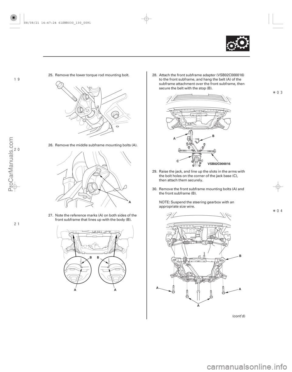
25. Remove the lower torque rod mounting bolt.
26. Remove the middle subframe mounting bolts (A).
27. Note the reference marks (A) on both sides of the
front subframe that lines up with the body (B). 28. Attach the front subframe adapter (VSB02C000016)
to the front subframe, and hang the belt (A) of the
subframe attachment over the front subframe, then
secure the belt with the stop (B).
29. Raise the jack, and line up the slots in the arms with the bolt holes on the corner of the jack base (C),
then attach them securely.
30. Remove the front subframe mounting bolts (A) and the front subframe (B).
NOTE: Suspend the steering gearbox with an
appropriate size wire.
(cont’d)
08/08/21 14:47:24 61SNR030_130_0091
ProCarManuals.com
DYNOMITE -2009-
Page 862 of 2893
����
�
��
���
�
��
�
��
13-93
14x1.5mm
88 N·m
(9.0 kgf·m,
65 lbf·ft)
12x1.25mm
74 N·m
(7.5 kgf·m,
55 lbf·ft)
A
A 12x1.25mm
64 N·m
(6.5 kgf·m,
47 lbf·ft)
10x1.25mm
54 N·m
(5.5 kgf·m,
40 lbf·ft)
10x1.25mm
59 N·m
(6.0 kgf·m,
43 lbf·ft)
A
B
12. Install a new lower torque rod bracket mounting bolt.
13. Install the front engine mount bracket (A) on the transmission and the engine with new bolts.
14. Loosely tighten a new front engine mount bracket mounting bolt (A), then attach the lower radiator
hose to the front engine mount bracket. 15. Install new middle subframe mounting bolts.
16. Install the steering gearbox stiffener plate (A) and
the harness clip (B).
(cont’d)
Replace. Replace.
Replace. Replace.
08/08/21 14:47:27 61SNR030_130_0095
ProCarManuals.com
DYNOMITE -2009-
Page 960 of 2893

�´�µ�µ
�´
�´
�����
Electronic Control System (cont’d)
S Position Automatic Shift Mode and Sequential Sportshift Mode
14-44 Automatic Transmission
System Description (cont’d)
SHIFT INDICATOR
’’M’’ INDICATOR
The S position has two shifting modes; the automatic shift mode and the sequential sportshift mode. In the S position
automatic shift mode, the transmission upshifts and downshifts automatically from 1st through 4th gear, and the
paddle shifters are ready to be activated to switch to the sequential sportshift mode. In the automatic shift mode, the
shift indicator and the M indicator in the gauge control module (tach) do not come on.
When the paddle shifter (upshift switch) or the paddle shifter (downshift switch) is pressed, the automatic shift
mode is canceled and the sequential sportshift mode comes into operation. The shift indicator displays the number of
the selected gear, and the M indicator comes on. In the sequential sportshift mode, the driver can shift up and down
manually from 1st through 5th gear by using the paddle shifters, much like a manual transmission. The paddle shifters
are installed on the back of the steering wheel, and the driver can shift gears by pressing the paddle shifters without
taking either hand off the steering wheel.
In the sequential sportshift mode, the transmission must be shifted up and down by pressing the paddle shifters.
However, the transmission cannot downshift and stays in the current gear if the paddle shifter is pressed while the
vehicle is coasting at a speed that would cause the engine to over-rev by downshifting the transmission, and the shift
indicator blinks the number of the selected gear several times, then returns to the number of the current gear. If the
vehicle speed reaches an appropriate speed while the shift indicator is blinking the number of the selected gear, the
transmission downshifts and the shift indicator displays the selected gear. The transmission also cannot upshift and
stays in the current gear if the paddle shifter is pressed while driving below an appropriate upshifting speed, the
shift indicator blinks the number of the selected gear several times, then returns to the number of the current gear. If
the vehicle speed reaches an appropriate upshift speed while the shift indicator is blinking the number of the selected
gear, the transmission upshifts and the shift indicator displays the selected gear.
This mode has automatic downshifting areas so the vehicle can run smoothly with more power to cope with upcoming
acceleration. When coasting in 5th gear or 4th gear, the transmission downshifts to the next lower gear if the vehicle
slows down to the programmed speed, or by pressing the brake pedal.
When the transmission decelerates to a stop, the transmission shifts to 1st gear automatically. The transmission can
be shifted to 2nd gear by pressing the paddle shifter while the vehicle is stopped, and the vehicle can start off in 2nd
gear.
The sequential sportshift mode is canceled when moving the shift lever to any position other than S.
08/08/21 14:38:23 61SNR030_140_0046
ProCarManuals.com
DYNOMITE -2009-
Page 1153 of 2893
�
��
�
���
��
�
��
14-237
A
BC A
B
C
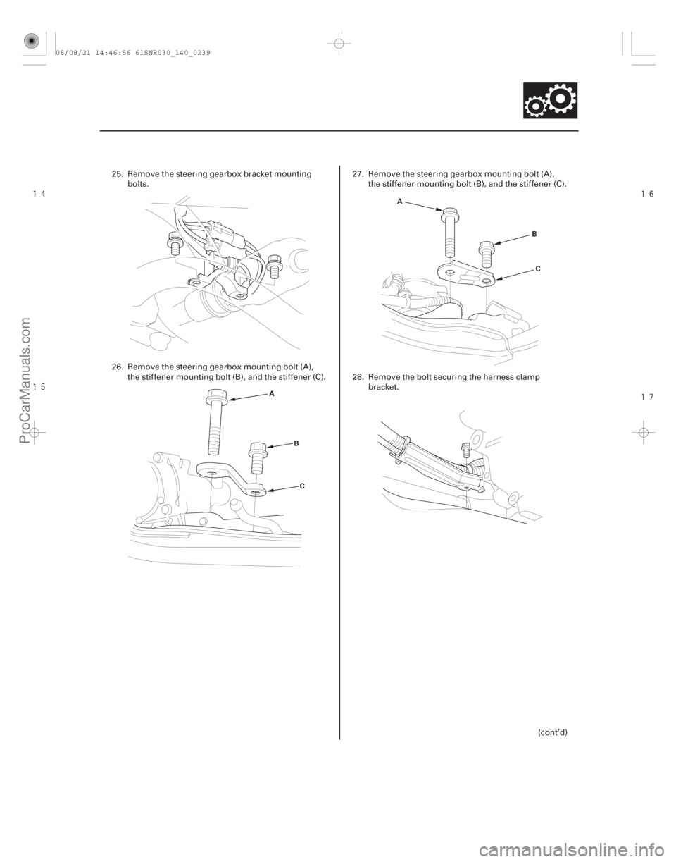
25. Remove the steering gearbox bracket mounting bolts.
26. Remove the steering gearbox mounting bolt (A), the stiffener mounting bolt (B), and the stiffener (C). 27. Remove the steering gearbox mounting bolt (A),
the stiffener mounting bolt (B), and the stiffener (C).
28. Remove the bolt securing the harness clamp bracket.
(cont’d)
08/08/21 14:46:56 61SNR030_140_0239
ProCarManuals.com
DYNOMITE -2009-
Page 1155 of 2893
����
��������
����
14-239
VSB02C000016
A
B
C
ABC
D
E
F
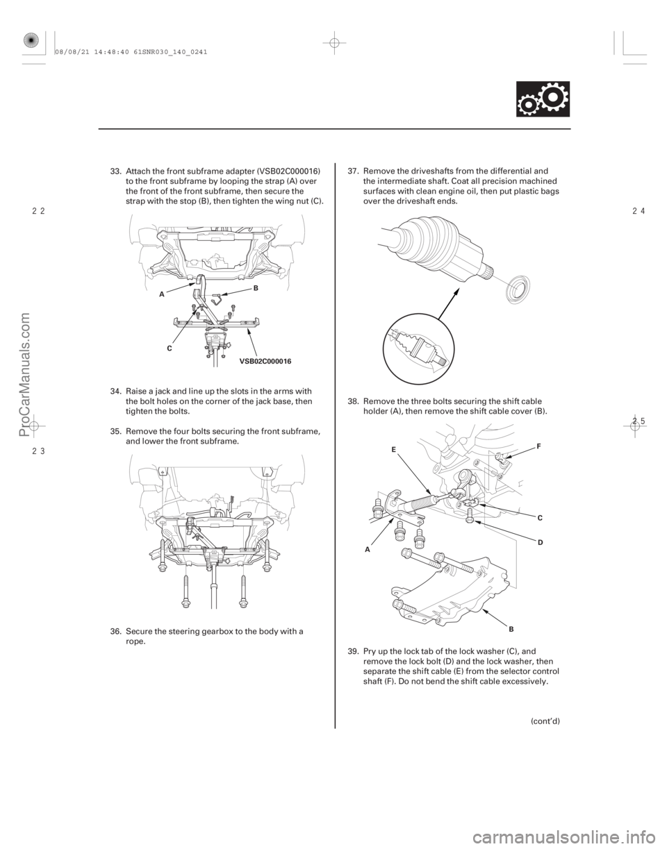
33. Attach the front subframe adapter (VSB02C000016)
to the front subframe by looping the strap (A) over
the front of the front subframe, then secure the
strap with the stop (B), then tighten the wing nut (C).
34. Raise a jack and line up the slots in the arms with the bolt holes on the corner of the jack base, then
tighten the bolts.
35. Remove the four bolts securing the front subframe, and lower the front subframe.
36. Secure the steering gearbox to the body with a rope. 37. Remove the driveshafts from the differential and
the intermediate shaft. Coat all precision machined
surfaces with clean engine oil, then put plastic bags
over the driveshaft ends.
38. Remove the three bolts securing the shift cable holder (A), then remove the shift cable cover (B).
39. Pry up the lock tab of the lock washer (C), and remove the lock bolt (D) and the lock washer, then
separate the shift cable (E) from the selector control
shaft (F). Do not bend the shift cable excessively.
(cont’d)
08/08/21 14:48:40 61SNR030_140_0241
ProCarManuals.com
DYNOMITE -2009-