Page 72 of 2893
�(�#�'�����������
���
�����������������������)���
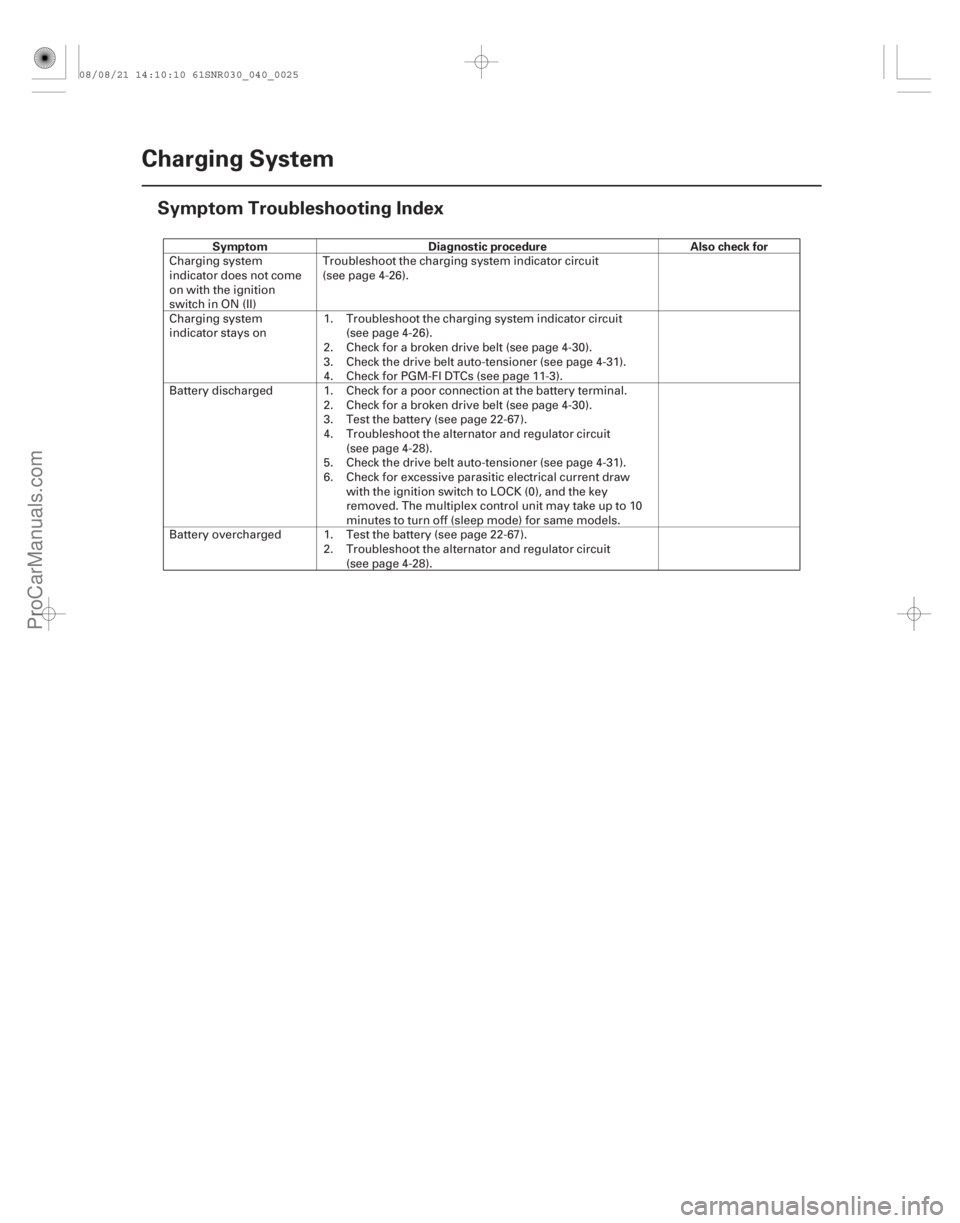
Symptom Diagnostic procedure Also check for
4-24
Charging System
Symptom Troubleshooting Index
Charging system
indicator does not come
on with the ignition
switch in ON (II)
Troubleshoot the charging system indicator circuit
(see page 4-26).
Charging system
indicator stays on 1.
2.
3.
4.Troubleshoot the charging system indicator circuit
(see page 4-26).
Check for a broken drive belt (see page 4-30).
Check the drive belt auto-tensioner (see page 4-31).
Check for PGM-FI DTCs (see page 11-3).
Battery discharged 1. 2.
3.
4.
5.
6.Check for a poor connection at the battery terminal.
Check for a broken drive belt (see page 4-30).
Test the battery (see page 22-67).
Troubleshoot the alternator and regulator circuit
(see page 4-28).
Check the drive belt auto-tensioner (see page 4-31).
Check for excessive parasitic electrical current draw
with the ignition switch to LOCK (0), and the key
removed. The multiplex control unit may take up to 10
minutes to turn off (sleep mode) for same models.
Battery overcharged 1. 2.Test the battery (see page 22-67).
Troubleshoot the alternator and regulator circuit
(see page 4-28).
08/08/21 14:10:10 61SNR030_040_0025
ProCarManuals.com
DYNOMITE -2009-
Page 74 of 2893
���
�(�#�'�����������
���
�������
���������������)����
�µ
�µ
�µ
�µ
�µ
�µ
�µ
�µ �µ
�µ
YES
NO
YES
NO
YES
NO
YES
NO
YES
NO
4-26Charging System
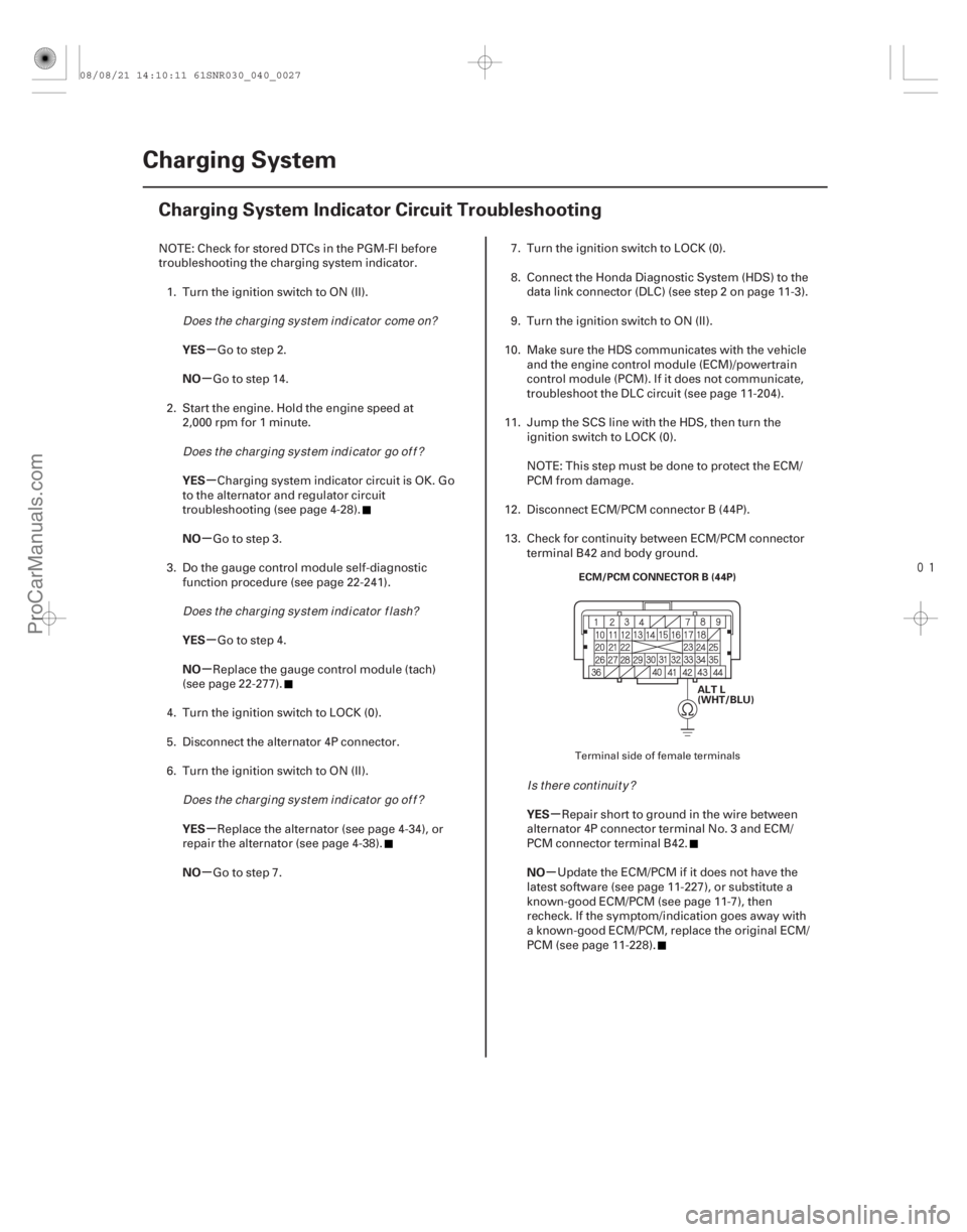
Charging System Indicator Circuit Troubleshooting
ALT L
(WHT/BLU)
ECM/PCM CONNECTOR B (44P)
NOTE: Check for stored DTCs in the PGM-FI before
troubleshooting the charging system indicator.
1. Turn the ignition switch to ON (II).
Go to step 2.
Go to step 14.
2. Start the engine. Hold the engine speed at 2,000 rpm for 1 minute.
Charging system indicator circuit is OK. Go
to the alternator and regulator circuit
troubleshooting (see page 4-28).
Go to step 3.
3. Do the gauge control module self-diagnostic function procedure (see page 22-241).
Go to step 4.
Replace the gauge control module (tach)
(see page 22-277).
4. Turn the ignition switch to LOCK (0).
5. Disconnect the alternator 4P connector.
6. Turn the ignition switch to ON (II).
Replace the alternator (see page 4-34), or
repair the alternator (see page 4-38).
Go to step 7. 7. Turn the ignition switch to LOCK (0).
8. Connect the Honda Diagnostic System (HDS) to the
data link connector (DLC) (see step 2 on page 11-3).
9. Turn the ignition switch to ON (II).
10. Make sure the HDS communicates with the vehicle and the engine control module (ECM)/powertrain
control module (PCM). If it does not communicate,
troubleshoot the DLC circuit (see page 11-204).
11. Jump the SCS line with the HDS, then turn the ignition switch to LOCK (0).
NOTE: This step must be done to protect the ECM/
PCMfromdamage.
12. Disconnect ECM/PCM connector B (44P).
13. Check for continuity between ECM/PCM connector terminal B42 and body ground.
Repair short to ground in the wire between
alternator 4P connector terminal No. 3 and ECM/
PCM connector terminal B42.
Update the ECM/PCM if it does not have the
latest software (see page 11-227), or substitute a
known-good ECM/PCM (see page 11-7), then
recheck. If the symptom/indication goes away with
a known-good ECM/PCM, replace the original ECM/
PCM (see page 11-228).
Terminal side of female terminals
Does t he char gi ng sy st em i nd i cat or come on?
Does t he char gi ng sy st em i nd i cat or go of f ?
Does t he char gi ng sy st em i nd i cat or f l ash?
Does t he char gi ng sy st em i nd i cat or go of f ? Is there continuity?
08/08/21 14:10:11 61SNR030_040_0027
ProCarManuals.com
DYNOMITE -2009-
Page 75 of 2893
����
�����
�µ
�µ
�µ
�µ �µ
�µ
YES
NO
YES
NO
YES
NO
4-27
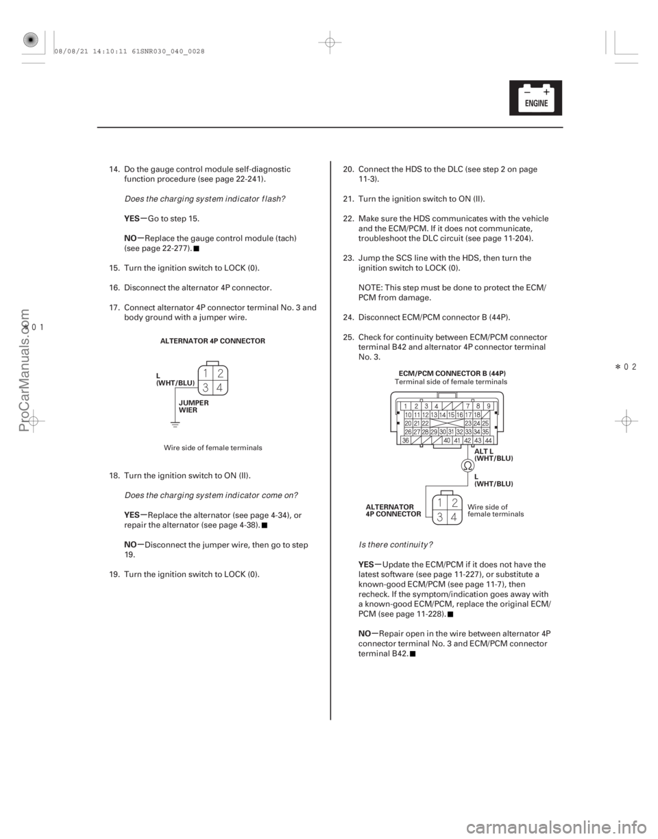
ALTERNATOR 4P CONNECTOR
L
(WHT/BLU) JUMPER
WIER
ALT L
(WHT/BLU)
ECM/PCM CONNECTOR B (44P)
L
(WHT/BLU)
ALTERNATOR
4P CONNECTOR
14. Do the gauge control module self-diagnostic function procedure (see page 22-241).
Go to step 15.
Replace the gauge control module (tach)
(see page 22-277).
15. Turn the ignition switch to LOCK (0).
16. Disconnect the alternator 4P connector.
17. Connect alternator 4P connector terminal No. 3 and body ground with a jumper wire.
18. Turn the ignition switch to ON (II). Replace the alternator (see page 4-34), or
repair the alternator (see page 4-38).
Disconnect the jumper wire, then go to step
19.
19. Turn the ignition switch to LOCK (0). 20. Connect the HDS to the DLC (see step 2 on page
11-3).
21. Turn the ignition switch to ON (II).
22. Make sure the HDS communicates with the vehicle and the ECM/PCM. If it does not communicate,
troubleshoot the DLC circuit (see page 11-204).
23. Jump the SCS line with the HDS, then turn the ignition switch to LOCK (0).
NOTE: This step must be done to protect the ECM/
PCMfromdamage.
24. Disconnect ECM/PCM connector B (44P).
25. Check for continuity between ECM/PCM connector terminal B42 and alternator 4P connector terminal
No. 3.
Update the ECM/PCM if it does not have the
latest software (see page 11-227), or substitute a
known-good ECM/PCM (see page 11-7), then
recheck. If the symptom/indication goes away with
a known-good ECM/PCM, replace the original ECM/
PCM (see page 11-228).
Repair open in the wire between alternator 4P
connector terminal No. 3 and ECM/PCM connector
terminal B42.
Wire side of female terminals Terminal side of female terminals
Wire side of
female terminals
Does t he char gi ng sy st em i nd i cat or f l ash?
Does t he char gi ng sy st em i nd i cat or come on? Is there continuity?
08/08/21 14:10:11 61SNR030_040_0028
ProCarManuals.com
DYNOMITE -2009-
Page 77 of 2893
���
����
�(�#�'�����������
���
�������
���������������)����
�µ
�µ �µ
�µ
YES
NO YES
NO
4-29
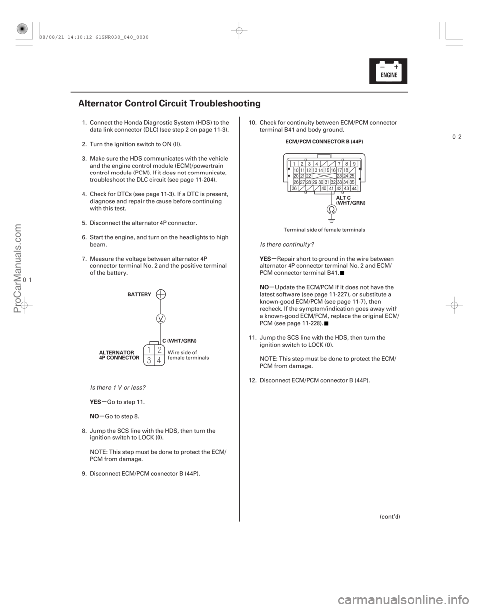
Alternator Control Circuit Troubleshooting
BATTERY
ALTERNATOR
4P CONNECTOR C (WHT/GRN) ALT C
(WHT/GRN)
ECM/PCM CONNECTOR B (44P)
1. Connect the Honda Diagnostic System (HDS) to the
data link connector (DLC) (see step 2 on page 11-3).
2. Turn the ignition switch to ON (II).
3. Make sure the HDS communicates with the vehicle and the engine control module (ECM)/powertrain
control module (PCM). If it does not communicate,
troubleshoot the DLC circuit (see page 11- 204).
4. Check for DTCs (see page 11-3). If a DTC is present, diagnose and repair the cause before continuing
with this test.
5. Disconnect the alternator 4P connector.
6. Start the engine, and turn on the headlights to high beam.
7. Measure the voltage between alternator 4P connector terminal No. 2 and the positive terminal
of the battery.
Go to step 11.
Go to step 8.
8. Jump the SCS line with the HDS, then turn the ignition switch to LOCK (0).
NOTE: This step must be done to protect the ECM/
PCM from damage.
9. Disconnect ECM/PCM connector B (44P). 10. Check for continuity between ECM/PCM connector
terminal B41 and body ground.
Repair short to ground in the wire between
alternator 4P connector terminal No. 2 and ECM/
PCM connector terminal B41.
Update the ECM/PCM if it does not have the
latest software (see page 11-227), or substitute a
known-good ECM/PCM (see page 11-7), then
recheck. If the symptom/indication goes away with
a known-good ECM/PCM, replace the original ECM/
PCM (see page 11-228).
11. Jump the SCS line with the HDS, then turn the ignition switch to LOCK (0).
NOTE: This step must be done to protect the ECM/
PCMfromdamage.
12. Disconnect ECM/PCM connector B (44P).
(cont’d)
Wire side of
female terminals Terminal side of female terminals
Is t her e 1 V or l ess?
Is there continuity?
08/08/21 14:10:12 61SNR030_040_0030
ProCarManuals.com
DYNOMITE -2009-
Page 79 of 2893
����
�(�#�'�����������
���
���������������
� �����)���
���
����
�(�#�'�����������
���
�����������������"�����)����
Special Tools Required
Special Tools Required
4-314-31
Drive Belt ReplacementDrive Belt Auto-tensioner
Inspection
YA9317
A B
A
YA9317
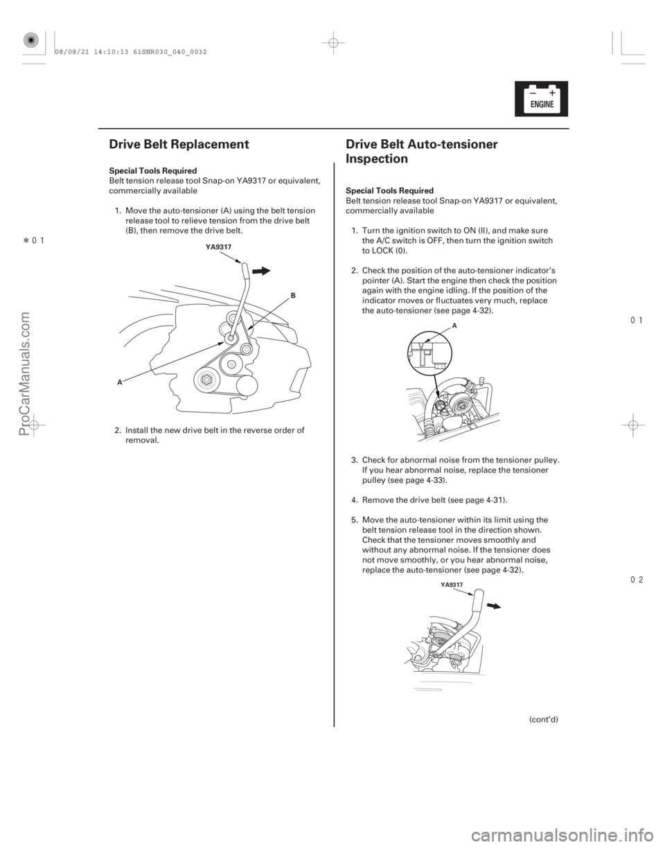
Belt tension release tool Snap-on YA9317 or equivalent,
commercially available
1. Move the auto-tensioner (A) using the belt tension release tool to relieve tension from the drive belt
(B), then remove the drive belt.
2. Install the new drive belt in the reverse order of removal. Belt tension release tool Snap-on YA9317 or equivalent,
commercially available
1. Turn the ignition switch to ON (II), and make sure the A/C switch is OFF, then turn the ignition switch
to LOCK (0).
2. Check the position of the auto-tensioner indicator’s pointer (A). Start the engine then check the position
again with the engine idling. If the position of the
indicator moves or fluctuates very much, replace
the auto-tensioner (see page 4-32).
3. Check for abnormal noise from the tensioner pulley. If you hear abnormal noise, replace the tensioner
pulley(seepage4-33).
4. Remove the drive belt (see page 4-31).
5. Move the auto-tensioner within its limit using the belt tension release tool in the direction shown.
Check that the tensioner moves smoothly and
without any abnormal noise. If the tensioner does
not move smoothly, or you hear abnormal noise,
replace the auto-tensioner (see page 4-32).
(cont’d)
08/08/21 14:10:13 61SNR030_040_0032
ProCarManuals.com
DYNOMITE -2009-
Page 87 of 2893
����
�(�#�'�����������
���
�������
�������
�!�����)����
Exploded View
4-38Charging System
Alternator Overhaul
ROTOR
FRONT BEARING
RETAINERFRONT BEARING
DRIVE-END
HOUSING
PULLEYPULLEY
LOCKNUT
TERMINAL
INSULATOR BRUSH HOLDER
ASSEMBLY REAR HOUSING
ASSEMBLY
END COVER WASHER
08/08/21 14:10:17 61SNR030_040_0039
ProCarManuals.com
DYNOMITE -2009-
Page 88 of 2893
����
��������
����
Special Tools Required
4-39
B
A
Driver 07749-0010000
Attachment, 42 x 47 mm 07746-0010300
NOTE: Refer to the Exploded View as needed during
this procedure.1. Test the alternator and regulator before you remove them (see page 4-28).
2. Remove the alternator (see page 4-34).
3. If the front bearing needs replacing, remove the pulley locknut with a 10 mm wrench (A) and a
22 mm wrench (B). If necessary, use an impact
wrench.
4. Remove the harness stay and the three flange nuts from the alternator. 5. Remove the end cover.
6. Remove the brush holder assembly.
(cont’d)
08/08/21 14:10:18 61SNR030_040_0040
ProCarManuals.com
DYNOMITE -2009-
Page 91 of 2893
�
��
�
��Alternator Reassembly
4-42Charging System
Alternator Overhaul (cont’d)
A
B
16. If you removed the pulley, put the rotor in the drive- end housing, then tighten its locknut to 110 N·m
(11.2 kgf·m, 81.0 lbf·ft).
17. Remove any grease or any oil from the slip rings.
18. Put the rear housing assembly and the drive-end housing/rotor assembly together, tighten the four
through bolts.
19. Push the brushes (A) in, then insert a pin or drill bit (B) (about 1.6 mm (0.06 in.) diameter) to hold them
there.
20. Install the brush holder assembly, and pull out the pin or drill bit.
21. Install the end cover.
22. After assembling the alternator, turn the pulley by hand to make sure the rotor turns smoothly and
without noise.
23. Install the alternator (see page 4-36) and the drive belt (see page 4-31).
08/08/21 14:10:46 61SNR030_040_0043
ProCarManuals.com
DYNOMITE -2009-