Page 73 of 2893
����
�(�#�'�����������
���
�����������������������)����
4-25
Circuit Diagram
6
3
191 F5
17 D2
A3
A2 H1
ELD
CANL
CANH
ALTF ALTC ALTL
5V
ALTERNATOR DRIVER
YEL
FR L C IG BRN
ELD
A23 GAUGE CONTROL MODULE (TACH)
IGNITION SWITCH
BATIG1
B43 B42 B41 A37
A36 RED
WHT CPU
YEL
1
BLK/YEL
No. 2 (50 A)
BLK
RECTIFIER
BATTERY
VOLTAGE REGULATOR2
3
4
B
BLK
G301
UNDER-HOOD FUSE/RELAY BOX
No. 1 (100 A)
ORN
WHT/RED WHT/GRNWHT/BLU UNDER-DASH
FUSE/RELAY BOX
CHARGING
SYSTEM
INDICATOR
IG1 HOT in ON (II)
and START (III)
A1
ECM/PCM BLU
Q9
WHT
22
17C101
CANH
CANL
YEL
No. 10
(7.5 A)
No. 3
(10 A)
08/08/21 14:10:10 61SNR030_040_0026
ProCarManuals.com
DYNOMITE -2009-
Page 76 of 2893

�µ�Ì
�Ï
����
�(�#�'�����������
���
�������
���������������)����
�µ
�µ �µ
�µ
Special Tools Required
YES
NO YES
NO
4-28
Charging System
Alternator and Regulator Circuit Troubleshooting
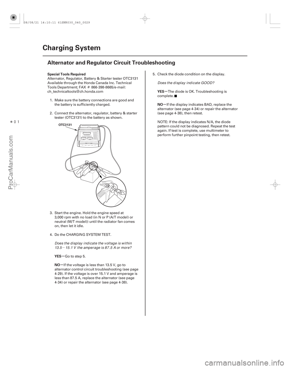
OTC3131
Alternator, Regulator, Battery & Starter tester OTC3131
Available through the Honda Canada Inc. Technical
Tools Department; FAX
866-398-8665/e-mail:
ch_technicaltools ch.honda.com
1. Make sure the battery connections are good and the battery is sufficiently charged.
2. Connect the alternator, regulator, battery & starter tester (OTC3131) to the battery as shown.
3. Start the engine. Hold the engine speed at 3,000 rpm with no load (in N or P (A/T model) or
neutral (M/T model)) until the radiator fan comes
on, then let it idle.
4. Do the CHARGING SYSTEM TEST.
Go to step 5.
If the voltage is less than 13.5 V, go to
alternator control circuit troubleshooting (see page
4-29). If the voltage is over 15.1 V and amperage is
less than 87.5 A, replace the alternator (see page
4-34) or repair the alternator (see page 4-38). 5. Check the diode condition on the display.
The diode is OK. Troubleshooting is
complete.
If the display indicates BAD, replace the
alternator (see page 4-34) or repair the alternator
(see page 4-38), then retest.
NOTE: If the display indicates N/A, the diode
pattern could not be diagnosed. Repeat the test
again. If test is complete, use multimeter to
perform further pinpoint testing, then retest.
Does the display indicate the voltage is within 13.5 15 .1 V t he amper age i s 87 .5 A or mor e? Does t he d i spl ay i nd i cat e GOOD?
08/08/21 14:10:11 61SNR030_040_0029
ProCarManuals.com
DYNOMITE -2009-
Page 77 of 2893

���
����
�(�#�'�����������
���
�������
���������������)����
�µ
�µ �µ
�µ
YES
NO YES
NO
4-29
Alternator Control Circuit Troubleshooting
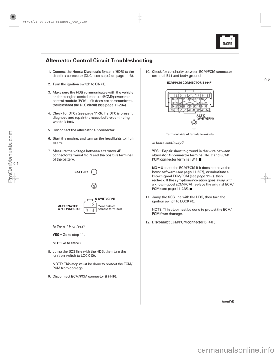
BATTERY
ALTERNATOR
4P CONNECTOR C (WHT/GRN) ALT C
(WHT/GRN)
ECM/PCM CONNECTOR B (44P)
1. Connect the Honda Diagnostic System (HDS) to the
data link connector (DLC) (see step 2 on page 11-3).
2. Turn the ignition switch to ON (II).
3. Make sure the HDS communicates with the vehicle and the engine control module (ECM)/powertrain
control module (PCM). If it does not communicate,
troubleshoot the DLC circuit (see page 11- 204).
4. Check for DTCs (see page 11-3). If a DTC is present, diagnose and repair the cause before continuing
with this test.
5. Disconnect the alternator 4P connector.
6. Start the engine, and turn on the headlights to high beam.
7. Measure the voltage between alternator 4P connector terminal No. 2 and the positive terminal
of the battery.
Go to step 11.
Go to step 8.
8. Jump the SCS line with the HDS, then turn the ignition switch to LOCK (0).
NOTE: This step must be done to protect the ECM/
PCM from damage.
9. Disconnect ECM/PCM connector B (44P). 10. Check for continuity between ECM/PCM connector
terminal B41 and body ground.
Repair short to ground in the wire between
alternator 4P connector terminal No. 2 and ECM/
PCM connector terminal B41.
Update the ECM/PCM if it does not have the
latest software (see page 11-227), or substitute a
known-good ECM/PCM (see page 11-7), then
recheck. If the symptom/indication goes away with
a known-good ECM/PCM, replace the original ECM/
PCM (see page 11-228).
11. Jump the SCS line with the HDS, then turn the ignition switch to LOCK (0).
NOTE: This step must be done to protect the ECM/
PCMfromdamage.
12. Disconnect ECM/PCM connector B (44P).
(cont’d)
Wire side of
female terminals Terminal side of female terminals
Is t her e 1 V or l ess?
Is there continuity?
08/08/21 14:10:12 61SNR030_040_0030
ProCarManuals.com
DYNOMITE -2009-
Page 83 of 2893
���
�(�#�'�����������
���
����������������� �����)���
���
�(�#�'�����������
���
�������
�������
� �����)����
Removal
4-344-34 Charging System
Idler Pulley Replacement
Alternator Removal and Installation
8x1.25mm
22 N·m
(2.2 kgf·m, 16 lbf·ft)
AB
C
A
C
C C
1. Remove the drive belt (see page 4-31).
2. Remove the idler pulley.
3. Install the idler pulley in the reverse order of
removal. 1. Do the battery terminal disconnection procedure
(see page 22-68).
2. Remove the drive belt (see page 4-31).
3. Remove the front grille cover (see page 20-163).
4. Disconnect the fan motor connectors (A) and the hood switch connector (B), then remove the
harnessclamps(C).
08/08/21 14:10:14 61SNR030_040_0035
ProCarManuals.com
DYNOMITE -2009-
Page 86 of 2893
�
��
4-37
AB
C
A
C
C C
6. Connect the fan motor connectors (A) and the hood
switch connector (B), then install the harness
clamps (C).
7. Install the front grille cover (see page 20-163).
8. Install the drive belt (see page 4-31).
9. Do the battery terminal reconnecting procedure (see page 22-68).
08/08/21 14:10:16 61SNR030_040_0038
ProCarManuals.com
DYNOMITE -2009-
Page 95 of 2893

����
�(�#�'�����������
���������������������������)����
�´
�µ
4-46 Cruise Control
Circuit Diagram
(A/T model) 764 5 12
G504 11
3
LIGHTS
CRUISE CONTROL INDICATOR
C21
C20
C12
12 V
5V
C4
G401 3 2 C1
A20
3
2 4
1 (50 A) No. 2
No. 19 (15 A) No. 21 (15 A)
A8
A6
C43 B28 GRY
ORN
ECM/PCM A37
A36
BAT
IG1
A39
A40
C39
C3
A41
THROTTLE BODY
TP SENSOR
No. 3
(10 A)
CRUISE MAIN INDICATOR
DRIVER
GAUGE CONTROL MODULE (TACH)
No. 12
(15 A)
UNDER-HOOD FUSE/RELAY BOX
BATTERY
No. 1 (100 A)
CPU
IG1 HOT in
ON (II) and
START (III)
CABLE
REEL
CAN-
CEL RESUME/
ACCEL
CABLE
REEL
THROTTLE
ACTUATOR
BRAKE
PEDAL
POSITION
SWITCH MULTIPLEX
INTEGRATED
CONTROL UNIT
TRANSMISSION
RANGE SWITCH SET/
DECEL
CRUISE
CONTROL
MAIN
CRUISE CONTROL
DIMMING CIRCUIT
PGM-FI
MAIN
RELAY 1
ETCS
CONTROL
RELAY
UNDER-DASH
FUSE/RELAY
BOX HORN
SWITCH
CRUISE CONTROL
COMBINATION SWITCH
IGNITION
SWITCH
IG1ETCS
ETCSRLY
IGP
MRLY CANL
CANH
BKSWNC
BKSW
TPSB
TPSA
VCC3
ETCSM
NC ATPFWD SG3
ETCSM
CRMTCLS
D8
H1 F9 F6 F5 E1
3
6
19101114
OUTPUT SHAFT
(COUNTERSHAFT)
SPEED SENSOR CLUTCH
PEDAL
POSITION
SWITCH No. 14 (7.5 A) FUSE
(UNDER-DASH
FUSE/RELAY BOX)
YEL
WHT BLU
YEL
LT BLU
BLK LT GRN ORN RED
LT GRN BRN ORN GRN WHT WHT
YEL RED
5V
BLU/WHT LT BLU BLU/YEL BLU
BLU/RED
GRN/YEL GRN RED/BLK RED/BLU
BLK
WHT
D2
F5 42 31
32
41 1
10
679 8 2
21 18 C101
(M/T model) CANL CANH
19
08/08/21 14:10:50 61SNR030_040_0047
ProCarManuals.com
DYNOMITE -2009-
Page 102 of 2893

�Ì�Ï
���
����
����
�(�#�'�����������
��������������������� �����)����
Special Tools Required
5-3
Engine Removal
C
A
B
B
AB
Engine hanger adapter VSB02C000015
Engine support hanger, A and Reds AAR-T 1256
2006 Civic engine hanger VSB02C000025
Front subframe adapter VSB02C000016
Universal lifting eyelet 07AAK-SNAA120 : These special tools are available through Honda
Canada Inc. Technical Tools Department; FAX 866-398-8665/e-mail: ch_technicaltools ch.honda.
com
NOTE: Use fender covers to avoid damaging painted surfaces.
To avoid damaging the wire and terminals, unplug the wiring connectors carefully while holding the
connector portion.
Mark all wiring and hoses to avoid misconnection. Also, be sure that they do not contact other wiring or
hoses, or interfere with other parts.
1. Secure the hood in the wide open position (support rod in the lower hole).
2. Relieve the fuel pressure (see page 11-322).
3. Do the battery removal procedure (see page 22-69).
4. Disconnect the vacuum hose and the breather pipe, then remove the intake air duct (see step 2 on page
9-3).
5. Remove the air cleaner assembly (see page 11-345).
6. Remove the under-cowl panel (see step 4 on page 20-164). 7. Disconnect the connector (A), and remove the
harness clamps (B), then remove the pipe (C).
8. Disconnect the battery cables (A) from the under- hood fuse/relay box.
9. Remove the harness clamp (B). (cont’d)
08/08/21 14:20:21 61SNR030_050_0003
ProCarManuals.com
DYNOMITE -2009-
Page 122 of 2893

��
������ ��
�
5-23
B
A
6x1.0mm
10 N·m
(1.0 kgf·m, 7.2 lbf·ft) A
B A
B
C
6x1.0mm
10 N·m
(1.0 kgf·m, 7.2 lbf·ft)
C
56. Install the ECM/PCM (A), then install the ECM/PCM
cover (B).
57. Connect the battery cables (A) to the under-hood fuse/relay box.
58. Install the harness clamp (B). 59. Install the pipe (A).
60. Connect the connector (B), and install the harness
clamps (C).
61. Install the under cowl-panel (see step 4 on page 20-164).
62. Install the air cleaner assembly (see page 11-345).
63. Install the front wheels.
64. Do the battery installation procedure (see page 22-69).
65. Inspect for fuel leaks. Turn the ignition switch to ON (II) (do not operate the starter) so the fuel pump
runs for about 2 seconds and pressurizes the fuel
line. Repeat this operation three times, then check
for fuel leakage at any point in the fuel line.
66. Refill the engine with engine oil (see step 4 on page 8-10).
(cont’d)
08/08/21 14:21:01 61SNR030_050_0023
ProCarManuals.com
DYNOMITE -2009-