Page 1170 of 2893
���
��������
����
�(�#�'�������
���
�����
�
���
��������� �����)����
14-254 Automatic Transmission
Shift Lever Removal
A
A
B C
A
B
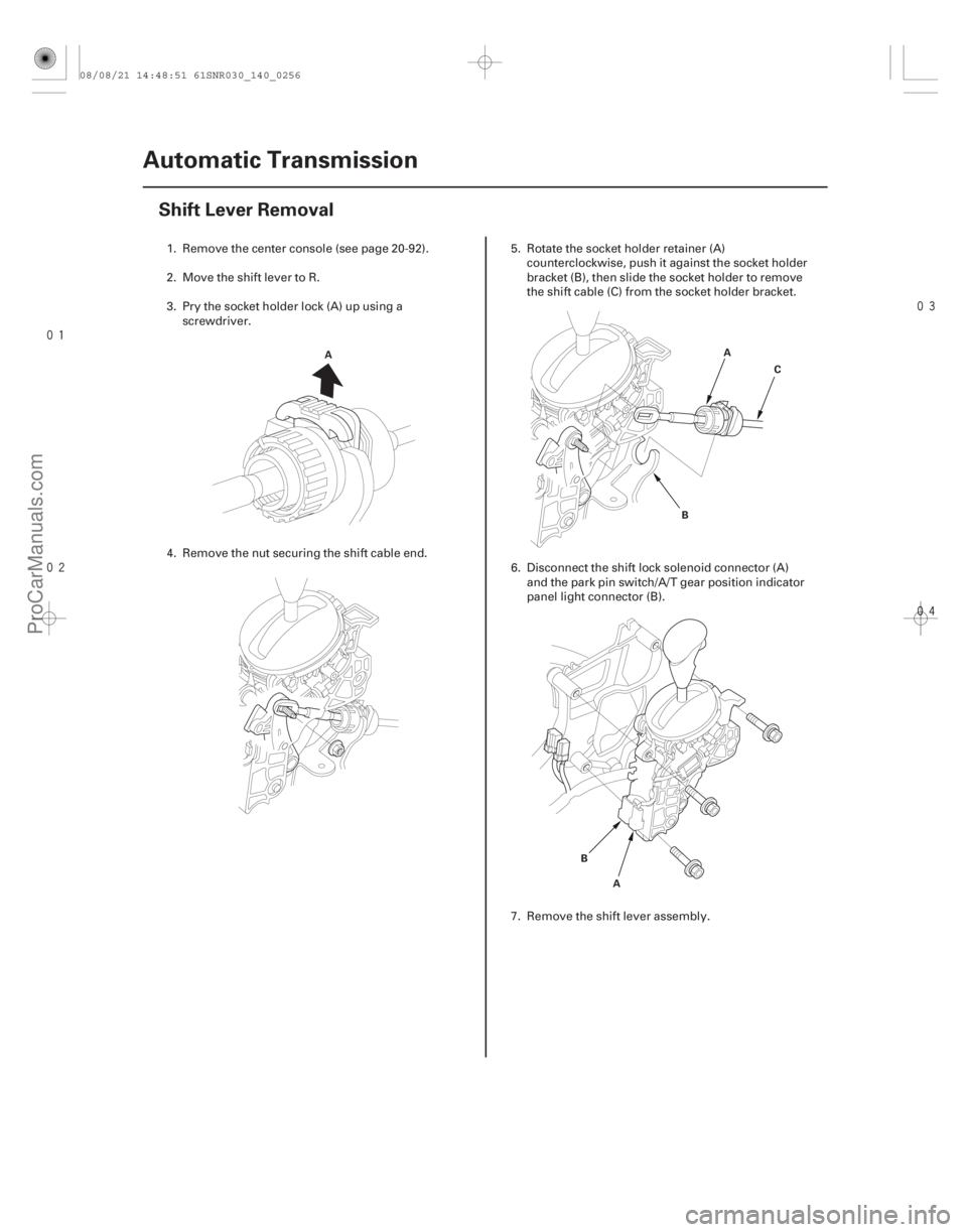
1. Remove the center console (see page 20-92).
2. Move the shift lever to R.
3. Pry the socket holder lock (A) up using a
screwdriver.
4. Remove the nut securing the shift cable end. 5. Rotate the socket holder retainer (A)
counterclockwise, push it against the socket holder
bracket (B), then slide the socket holder to remove
the shift cable (C) from the socket holder bracket.
6. Disconnect the shift lock solenoid connector (A) and the park pin switch/A/T gear position indicator
panel light connector (B).
7. Remove the shift lever assembly.
08/08/21 14:48:51 61SNR030_140_0256
ProCarManuals.com
DYNOMITE -2009-
Page 1172 of 2893
����
�(�#�'�������
���
�����
�
���
���������"�����)�
��
14-256Automatic Transmission
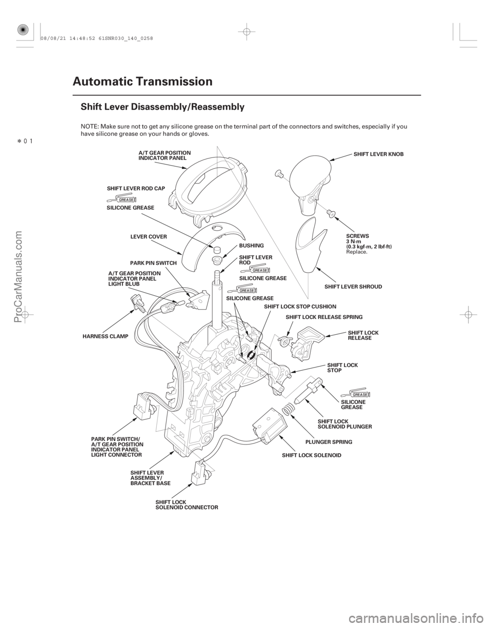
Shift Lever Disassembly/Reassembly
A/T GEAR POSITION
INDICATOR PANEL
SCREWS
3N·m
(0.3 kgf·m, 2 lbf·ft)SHIFT LEVER KNOB
SILICONE GREASE
SHIFT LOCK SOLENOID
HARNESS CLAMP
PARK PIN SWITCH/
A/T GEAR POSITION
INDICATOR PANEL
LIGHT CONNECTOR PARK PIN SWITCH
SHIFT LOCK RELEASE SPRING
SHIFT LOCK
SOLENOID PLUNGER
SHIFTLOCKSTOPCUSHION
SHIFT LOCK
STOP
SHIFT LEVER
ASSEMBLY/
BRACKET BASE SHIFT LEVER
ROD
LEVER COVER
A/T GEAR POSITION
INDICATOR PANEL
LIGHT BLUB
SHIFT LOCK
RELEASE
SHIFT LEVER SHROUD
PLUNGER SPRING SILICONE
GREASE
SHIFT LOCK
SOLENOID CONNECTOR BUSHING
SHIFT LEVER ROD CAP
SILICONE GREASESILICONE GREASE
NOTE: Make sure not to get any silicone grease on the terminal part of the connectors and switches, especially if you
have silicone grease on your hands or gloves.
Replace.
08/08/21 14:48:52 61SNR030_140_0258
ProCarManuals.com
DYNOMITE -2009-
Page 1174 of 2893

6x1.0mm
9.8 N·m (1.0 kgf·m, 7.2 lbf·ft)
6x1.0mm
9.8 N·m
(1.0 kgf·m, 7.2 lbf·ft)A
B C
D
6x1.0mm
12 N·m
(1.2 kgf·m, 8.")
��������
14-258Automatic Transmission
Shift Cable Replacement (cont’d)
6x1.0mm
9.8 N·m (1.0 kgf·m, 7.2 lbf·ft)
6x1.0mm
9.8 N·m
(1.0 kgf·m, 7.2 lbf·ft)A
B C
D
6x1.0mm
12 N·m
(1.2 kgf·m, 8.7 lbf·ft)6x1.0mm
9.8 N·m
(1.0 kgf·m,
7.2 lbf·ft)
D
6x1.0mm
14 N·m
(1.4 kgf·m,
10 lbf·ft)A
B
E
F
C
9. Remove the nuts securing the shift cable bracket
(A) and the grommet (B).
10. Remove the shift cable grommet, and pull out the shift cable (C).
11. Insert a new shift cable through the grommet hole (D), and install the grommet in its hole. Do not bend
the shift cable excessively.
12. Secure the shift cable bracket and the grommet with the nuts.
13. Make sure that the transmission is in the R position at the selector control shaft. 14. Install the control lever (A) over the selector control
shaft (B).
15. Secure the control lever with a new lock washer (C) and the lock bolt (D), then bend the lock tab of the
lock washer against the bolt head.
16. Install the shift cable cover (E), and install the shift cable holder (F) on the cover.
17. Install the shift cable on the shift lever, and adjust the cable (see step 5 on page 14-259).
Replace.
08/08/21 14:48:53 61SNR030_140_0260
ProCarManuals.com
DYNOMITE -2009-
Page 1176 of 2893
����
��������
����
14-260Automatic Transmission
Shift Cable Adjustment (cont’d)
A
B
C
A B
C B
A
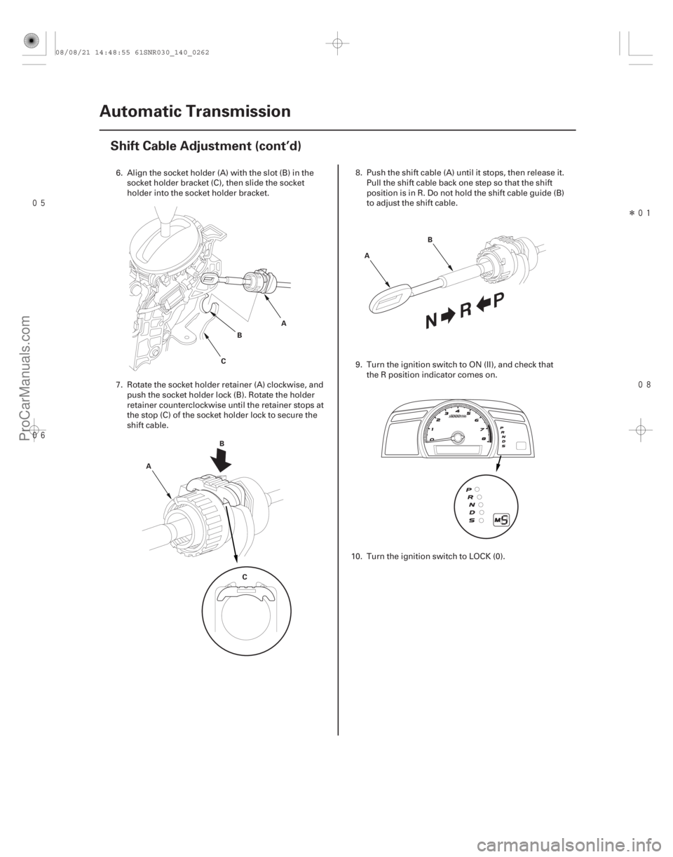
6. Align the socket holder (A) with the slot (B) in the socket holder bracket (C), then slide the socket
holder into the socket holder bracket.
7. Rotate the socket holder retainer (A) clockwise, and push the socket holder lock (B). Rotate the holder
retainer counterclockwise until the retainer stops at
the stop (C) of the socket holder lock to secure the
shift cable. 8. Push the shift cable (A) until it stops, then release it.
Pull the shift cable back one step so that the shift
position is in R. Do not hold the shift cable guide (B)
to adjust the shift cable.
9. Turn the ignition switch to ON (II), and check that the R position indicator comes on.
10. Turn the ignition switch to LOCK (0).
08/08/21 14:48:55 61SNR030_140_0262
ProCarManuals.com
DYNOMITE -2009-
Page 1178 of 2893
�
��
14-262Automatic Transmission
Shift Cable Adjustment (cont’d)
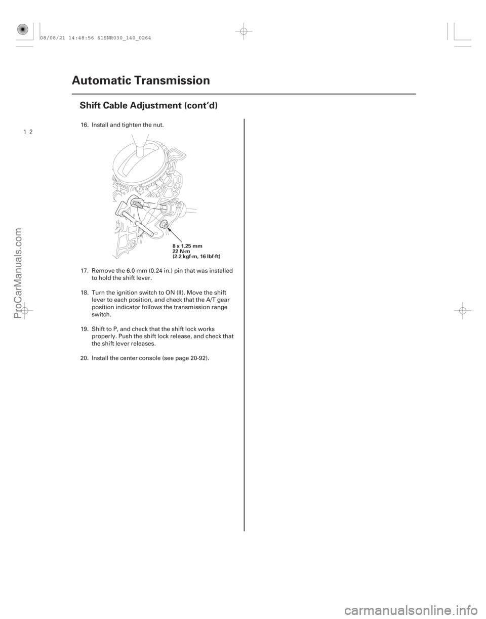
8x1.25mm
22 N·m
(2.2 kgf·m, 16 lbf·ft)
16. Install and tighten the nut.
17. Remove the 6.0 mm (0.24 in.) pin that was installed
to hold the shift lever.
18. Turn the ignition switch to ON (II). Move the shift lever to each position, and check that the A/T gear
position indicator follows the transmission range
switch.
19. Shift to P, and check that the shift lock works properly. Push the shift lock release, and check that
the shift lever releases.
20. Install the center console (see page 20-92).
08/08/21 14:48:56 61SNR030_140_0264
ProCarManuals.com
DYNOMITE -2009-
Page 1296 of 2893
���
���
����
�(�#������������
��������������������� �����)����
16-416-4 Driveline/Axle
Driveshaft Inspection
Driveshaft Removal
F
D B
C
A
E A
B
1.")
���
�(�#�'�����������
���������������������"�����)���
���
����
�(�#�'�����������
��������������������� �����)����
16-416-4 Driveline/Axle
Driveshaft Inspection
Driveshaft Removal
F
D B
C
A
E A
B
1. Check the inboard boot (A) and the outboard boot (B) on the driveshaft (C) for cracks, damage, leaking
grease, and loose boot bands (D). If any damage is
found, replace the boot and the boot bands.
2. Check the driveshaft for cracks and damage. If any damage is found, replace the driveshaft.
3. Check the inboard joint (E) and the outboard joint (F) for cracks and damage. If any damage is found,
replace the inboard joint or the outboard joint as an
assembly.
4. Hold the inboard joint and turn the front wheel by hand, then make sure the joint is not excessively
loose. If necessary, replace the inboard joint or the
outboard joint as an assembly. 1. Raise the vehicle on a lift.
2. Remove the front wheels.
3. Pry up the locking tab (A) on the spindle nut (B),
then remove the nut.
4. Drain the transmission fluid, then reinstall the drain plug with a new sealing washer:
5-speed manual transmission (see page 13-5)
6-speed manual transmission (see page 13-82)
Automatic transmission (see page 14-232)
5. Remove the nuts and the bolt, then separate the lower arm using a prybar.
08/08/21 14:51:21 61SNR030_160_0004
ProCarManuals.com
DYNOMITE -2009-
Page 1315 of 2893

B
A
K20Z2 engine model:
22x1.5mm
181 N·m
(18.5 kgf·m, 134 lbf·ft)
K20Z3 engine model:
24x1.5mm
245 N·m
(25.0 kgf·m, 180 lbf·ft)
9.")
�����
16-22Driveline/Axle
Driveshaft Installation (cont’d)
B
A
K20Z2 engine model:
22x1.5mm
181 N·m
(18.5 kgf·m, 134 lbf·ft)
K20Z3 engine model:
24x1.5mm
245 N·m
(25.0 kgf·m, 180 lbf·ft)
9. Apply small amount of engine oil to the seating surface of new spindle nut (A).
10. Install the spindle nut, then tighten it. After tightening, use a drift to stake the spindle nut
shoulder (B) against the driveshaft.
11. Clean the mating surfaces of the brake disc and the wheel, then install the front wheels.
12. Turn the front wheel by hand, and make sure there is no interference between the driveshaft and
surrounding parts. 13. Refill the transmission with the recommended
transmission fluid:
5-speed manual transmission (see page 13-5)
6-speed manual transmission (see page 13-82)
Automatic transmission (see page 14-232)
14. Lower the vehicle on the lift.
15. Check the wheel alignment, and adjust it if necessary (see page 18-5).
16. Test-drive the vehicle.
Replace.
Replace.
08/08/21 14:51:45 61SNR030_160_0022
ProCarManuals.com
DYNOMITE -2009-
Page 1316 of 2893
���
��������
�(�#�'�����������
��������������������� �����)����
16-23
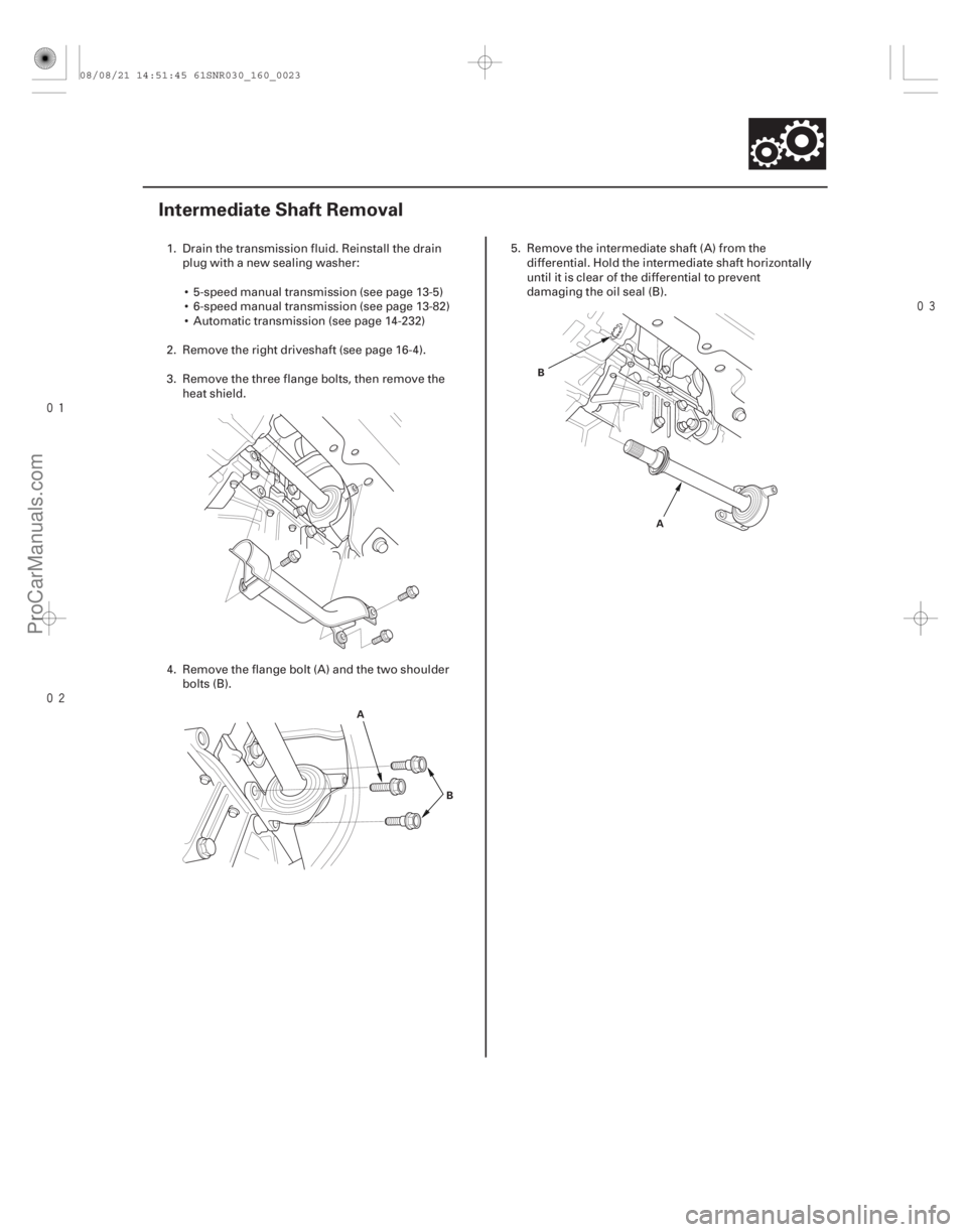
Intermediate Shaft Removal
A B A
B
1. Drain the transmission fluid. Reinstall the drain
plug with a new sealing washer:
5-speed manual transmission (see page 13-5)
6-speed manual transmission (see page 13-82)
Automatic transmission (see page 14-232)
2. Remove the right driveshaft (see page 16-4).
3. Remove the three flange bolts, then remove the heat shield.
4. Remove the flange bolt (A) and the two shoulder bolts (B). 5. Remove the intermediate shaft (A) from the
differential. Hold the intermediate shaft horizontally
until it is clear of the differential to prevent
damaging the oil seal (B).
08/08/21 14:51:45 61SNR030_160_0023
ProCarManuals.com
DYNOMITE -2009-