Page 1154 of 2893
�
��
�
������
���
14-238Automatic Transmission
Transmission Removal (cont’d)
A
BCC
B A
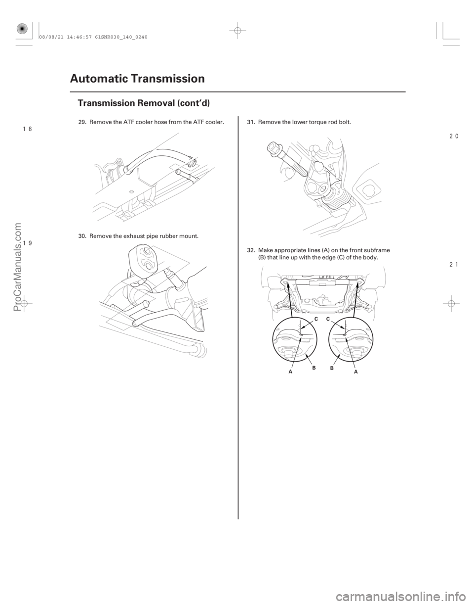
29. Remove the ATF cooler hose from the ATF cooler.
30. Remove the exhaust pipe rubber mount. 31. Remove the lower torque rod bolt.
32. Make appropriate lines (A) on the front subframe
(B) that line up with the edge (C) of the body.
08/08/21 14:46:57 61SNR030_140_0240
ProCarManuals.com
DYNOMITE -2009-
Page 1156 of 2893
����
��������
����
14-240Automatic Transmission
Transmission Removal (cont’d)
A
B
A B
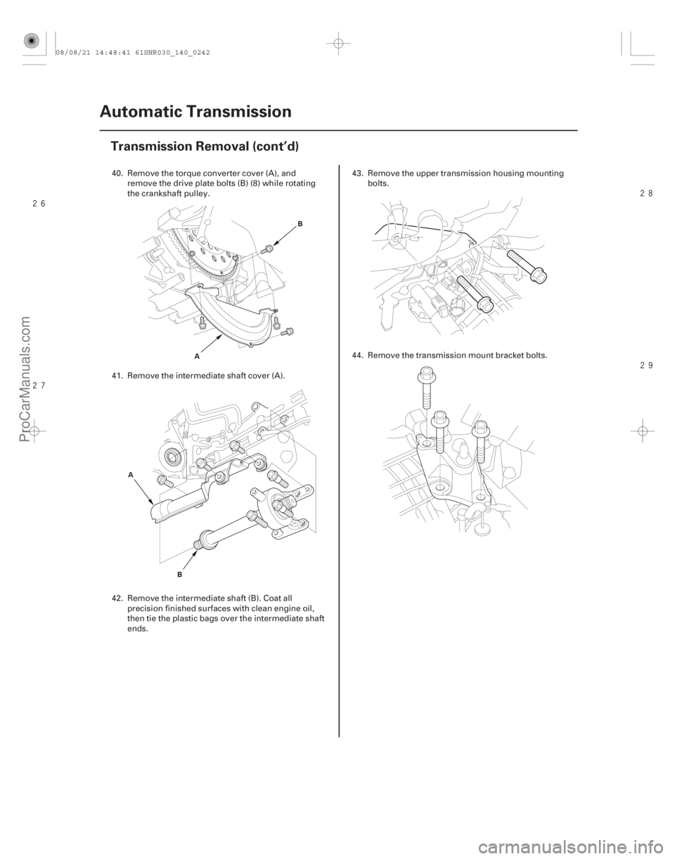
40. Remove the torque converter cover (A), andremove the drive plate bolts (B) (8) while rotating
the crankshaft pulley.
41. Remove the intermediate shaft cover (A).
42. Remove the intermediate shaft (B). Coat all precision finished surfaces with clean engine oil,
then tie the plastic bags over the intermediate shaft
ends. 43. Remove the upper transmission housing mounting
bolts.
44. Remove the transmission mount bracket bolts.
08/08/21 14:48:41 61SNR030_140_0242
ProCarManuals.com
DYNOMITE -2009-
Page 1158 of 2893
����
�Ì�Ï
���
�(�#��������
���
�����
��������������� �����)���� Special Tools Required
14-24214-242 Automatic Transmission
Drive Plate Removal and")
���
�(�#�'�������
���
�����
�������������
� �����)����
�Ì�Ï
���
�(�#�'�������
���
�����
��������������� �����)���� Special Tools Required
14-24214-242 Automatic Transmission
Drive Plate Removal and
Installation
Transmission Installation
A
B
12x1.0mm
74 N·m
(7.5 kgf·m, 54 lbf·ft) 6x1.0mm
12 N·m (1.2 kgf·m, 8.7 lbf·ft)
1. Remove the transmission assembly (see page
14-233).
2. Remove the drive plate (A) and the washer (B) from the engine crankshaft.
3. Install the drive plate and the washer on the engine crankshaft, and tighten the eight bolts in a
crisscross pattern in at least two steps.
4. Install the transmission assembly (see page 14-242). Engine hanger plate 07AAK-SNAA120
Engine support hanger, A and Reds AAR-T1256
2006 Civic engine hanger VSB02C000025
Front subframe adapter VSB02C000016
Available through Acura Canada Technical Tools
Department; Fax 866-398-8665/
e-mail: ch_technicaltools ch.honda.com
NOTE: Use fender covers to avoid damaging painted
surfaces. 1. Install the air cleaner housing mounting bracket.
08/08/21 14:48:42 61SNR030_140_0244
ProCarManuals.com
DYNOMITE -2009-
Page 1160 of 2893

12x1.25mm
59 N·m
(6.0 kgf·m, 43 lbf·ft)
10x1.25mm
39 N·m
(4.0 kgf·m, 29 lbf·ft)
E
8x1.25mm
22 N·m
(2.2 kgf·m, 16")
����
��������
14-244Automatic Transmission
Transmission Installation (cont’d)
12x1.25mm
59 N·m
(6.0 kgf·m, 43 lbf·ft)
10x1.25mm
39 N·m
(4.0 kgf·m, 29 lbf·ft)
E
8x1.25mm
22 N·m
(2.2 kgf·m, 16 lbf·ft)
F
8x1.25mm
22 N·m
(2.2 kgf·m, 16 lbf·ft)
D
8x1.25mm
22 N·m (2.2 kgf·m, 16 lbf·ft)
A
B
C A
B
8. Secure the transmission mount bracket on the
transmission housing with new mounting bolts.
9. Install a new set ring (A) on the intermediate shaft (B). 10. Clean the areas where the intermediate shaft
contacts the transmission (differential) with solvent,
and dry with compressed air. Apply intermediate
shaft splines with ATF, then install the intermediate
shaft, be sure not to allow dust or other foreign
particles to enter the transmission.
11. Install the intermediate shaft cover (C) with installing the m ounting bolts loosely.
12. First tighten the right upper bolt (D) on the cover, then the right lower bolt (E), and lastly the left bolt
(F).
13. Install a new set ring (A) on the left driveshaft (B).
14. Clean the areas where the left driveshaft contacts the transmission (differential) with solvent, and dry
with compressed air. Then install the left driveshaft,
be sure not to allow dust or other foreign particles
to enter the transmission. Turn the steering knuckle
fully outward, and slide the driveshaft into the
differential until you feel its set ring fully engage
thesidegear.
15. Apply right driveshaft inboard-joint splines with the recommended grease (P/N 08734-0001).
16. Slide the right driveshaft over the intermediate shaft splines until you feel the driveshaft fully
engage the intermediate shaft set ring.
Replace.
08/08/21 14:48:44 61SNR030_140_0246
ProCarManuals.com
DYNOMITE -2009-
Page 1162 of 2893
�
��
�
���
��
�
��
14-246Automatic Transmission
Transmission Installation (cont’d)
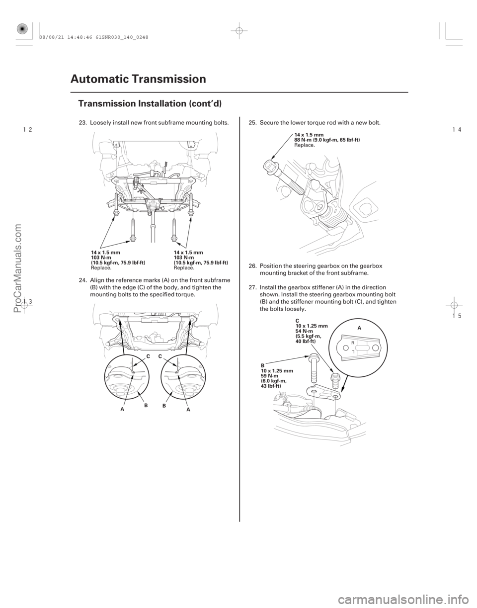
14x1.5mm
103 N·m
(10.5kgf·m,75.9lbf·ft)
14x1.5mm
103 N·m
(10.5 kgf·m, 75.9 lbf·ft)
A BCC
B A 14x1.5mm
88 N·m (9.0 kgf·m, 65 lbf·ft)
C
10x1.25mm
54 N·m
(5.5 kgf·m,
40 lbf·ft) A
B
10x1.25mm
59 N·m
(6.0 kgf·m,
43 lbf·ft)
23. Loosely install new front subframe mounting bolts.
24. Align the reference marks (A) on the front subframe (B) with the edge (C) of the body, and tighten the
mounting bolts to the specified torque. 25. Secure the lower torque rod with a new bolt.
26. Position the steering gearbox on the gearbox
mounting bracket of the front subframe.
27. Install the gearbox stiffener (A) in the direction shown. Install the steering gearbox mounting bolt
(B) and the stiffener mounting bolt (C), and tighten
the bolts loosely.
Replace. Replace. Replace.
08/08/21 14:48:46 61SNR030_140_0248
ProCarManuals.com
DYNOMITE -2009-
Page 1164 of 2893
����
���
����
����
14-248Automatic Transmission
Transmission Installation (cont’d)
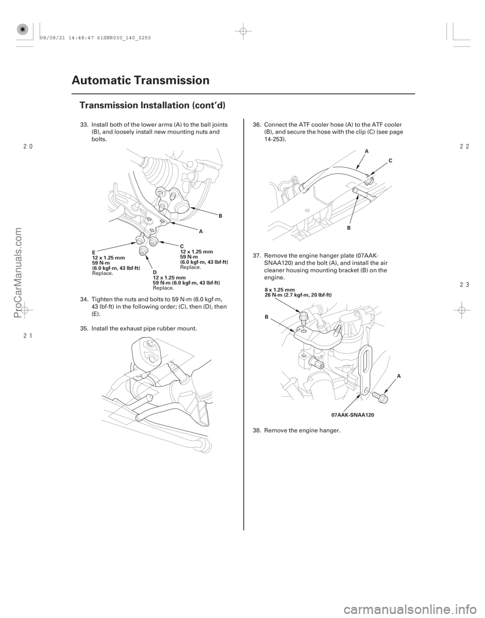
E
12x1.25mm
59 N·m
(6.0 kgf·m, 43 lbf·ft)
D
12x1.25mm
59N·m(6.0kgf·m,43lbf·ft)C
12x1.25mm
59 N·m
(6.0 kgf·m, 43 lbf·ft)
A
B A
B C
B A
07AAK-SNAA120
8x1.25mm
26 N·m (2.7 kgf·m, 20 lbf·ft)
33. Install both of the lower arms (A) to the ball joints
(B), and loosely install new mounting nuts and
bolts.
34. Tighten the nuts and bolts to 59 N·m (6.0 kgf·m, 43 lbf·ft) in the following order; (C), then (D), then
(E).
35. Install the exhaust pipe rubber mount. 36. Connect the ATF cooler hose (A) to the ATF cooler
(B), and secure the hose with the clip (C) (see page
14-253).
37. Remove the engine hanger plate (07AAK- SNAA120) and the bolt (A), and install the air
cleaner housing mounting bracket (B) on the
engine.
38. Remove the engine hanger.
Replace. Replace.Replace.
08/08/21 14:48:47 61SNR030_140_0250
ProCarManuals.com
DYNOMITE -2009-
Page 1166 of 2893
����
���
����
����
14-250Automatic Transmission
Transmission Installation (cont’d)
E
F
A
B
C
D
G A
B
C
DD
A
B
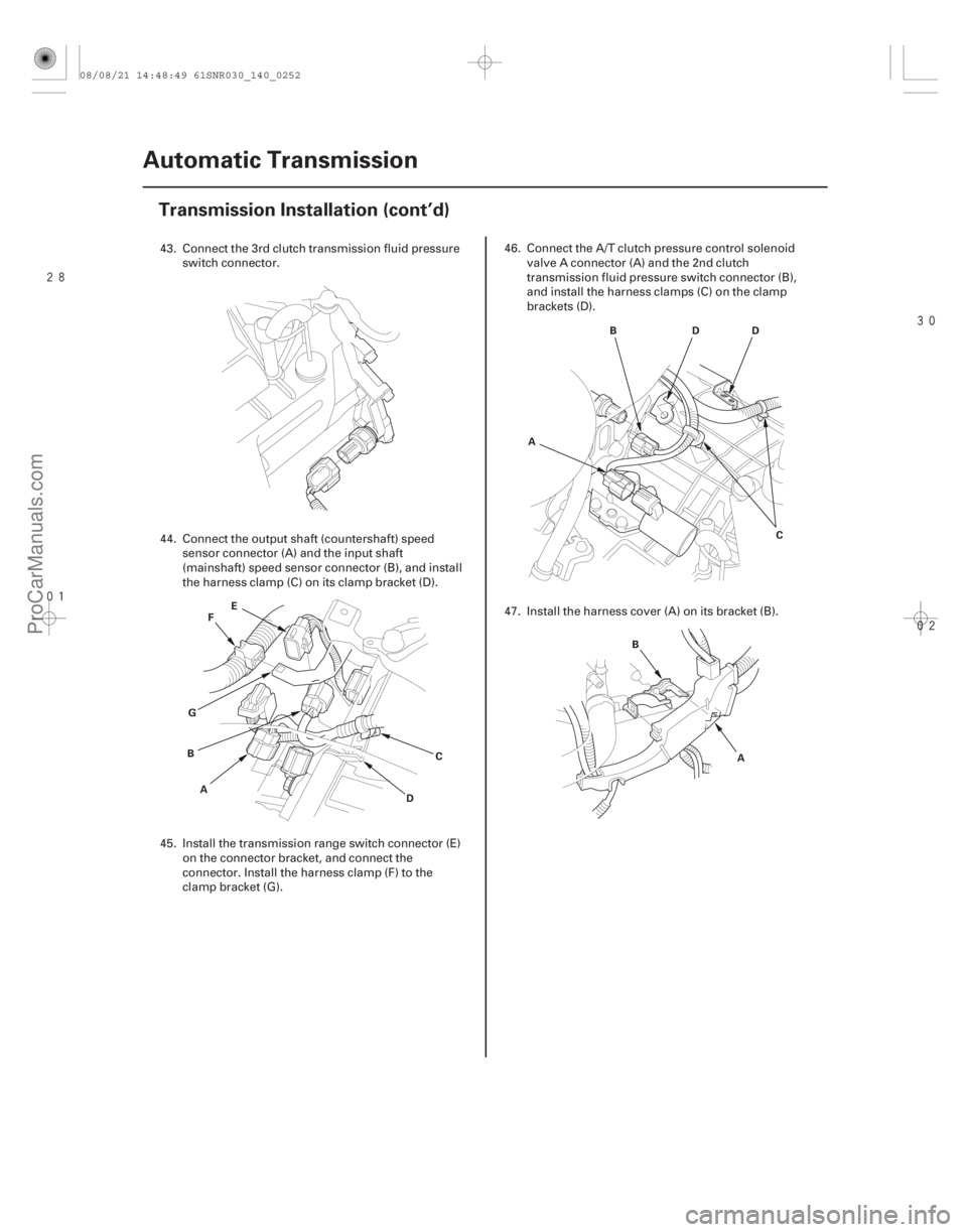
43. Connect the 3rd clutch transmission fluid pressure
switch connector.
44. Connect the output shaft (countershaft) speed sensor connector (A) and the input shaft
(mainshaft) speed sensor connector (B), and install
the harness clamp (C) on its clamp bracket (D).
45. Install the transmission range switch connector (E) on the connector bracket, and connect the
connector. Install the harness clamp (F) to the
clamp bracket (G). 46. Connect the A/T clutch pressure control solenoid
valve A connector (A) and the 2nd clutch
transmission fluid pressure switch connector (B),
and install the harness clamps (C) on the clamp
brackets (D).
47. Install the harness cover (A) on its bracket (B).
08/08/21 14:48:49 61SNR030_140_0252
ProCarManuals.com
DYNOMITE -2009-
Page 1168 of 2893

54. Refill the transmission with ATF (see step 5 on page
14-232).
55. Install the battery tray, the battery base, and the resonator.
5")
14-252Automatic Transmission
Transmission Installation (cont’d)
54. Refill the transmission with ATF (see step 5 on page
14-232).
55. Install the battery tray, the battery base, and the resonator.
56. Install the air cleaner assembly (see page 11-345) and the intake air duct (see page 11-348).
57. Install the front grille cover (see page 20-163).
58. Install the under-cowl lower panel and the cowl cover (see page 20-163).
59. Do the battery installation procedure (see page 22-69).
60. Install the front wheels.
61. Set the parking brake. Start the engine, and shift the transmission through all positions three times.
62. Check the shift lever operation, the A/T gear position indicator operation, and the shift cable
adjustment.
63. Check and adjust the front wheel alignment (see page 18-5).
64. Install the splash shield.
65. Start the engine with the shift lever in P or N, and warm it up to normal operating temperature (the
radiator fan comes on). Turn off the engine, and
check the ATF level (see page 14-231).
66. Road-test the vehicle (see page 14-208).
08/08/21 14:48:50 61SNR030_140_0254
ProCarManuals.com
DYNOMITE -2009-