Page 1197 of 2893
�
��
�µ
�µ �µ
�µ
�µ
�µ
YES
NO
YES
NO
YES
NO
14-280A/T Interlock System
Shift Lock System Circuit Troubleshooting
A
SHIFT LOCK SOLEN")
����
���
����
�(�#�'�������
���
�������������������
�������)�
��
�µ
�µ �µ
�µ
�µ
�µ
YES
NO
YES
NO
YES
NO
14-280A/T Interlock System
Shift Lock System Circuit Troubleshooting
A
SHIFT LOCK SOLENOID CONNECTOR
IG1 (YEL)
SHIFT LOCK SOLENOID CONNECTOR IG1 (YEL) SLS (PNK)
1. Connect the HDS to the DLC located under the
driver’s side of the dashboard.
2. Turn the ignition switch to ON (II). Make sure the HDS communicates with the PCM. If it does not, go
to the DLC circuit troubleshooting (see page
11-204).
3. Select Shift Lock Solenoid Test in the Miscellaneous Test Menu, and check that the shift
lock solenoid operates with the HDS.
Go to step 16.
Go to step 5.
4. Turn the ignition switch to LOCK (0).
5. Remove the center console (see page 20-92).
6. Disconnect the shift lock solenoid connector.
7. Turn the ignition switch to ON (II). 8. Measure the voltage between shift lock solenoid
connector terminal No. 1 and body ground.
Go to step 9.
CheckforablownNo.10(7.5A)fuseinthe
under-dash fuse/relay box. If the fuse is OK, repair
open in the wire between the shift lock solenoid
connector and the under-dash fuse/relay box.
9. Shift the shift lever to P, and press the brake pedal. Do not press the accelerator.
10. Measure the voltage between shift lock solenoid connector terminals No. 1 and No. 2 while pressing
the brake pedal.
Go to step 11.
Go to step 12.
Wire side of female terminals
Wire side of female terminals
Does t he shi f t l ock sol enoi d w or k pr oper l y ? Is t her e about bat t er y v ol t age?
Is there battery voltage?
08/08/21 14:50:06 61SNR030_140_0282
ProCarManuals.com
DYNOMITE -2009-
Page 1208 of 2893
����
14-28914-289
Park Pin Switch Test
6. Apply silicone grease to the pin on the shift lever bracket base, and install the shift lock stop over the")
���
�(�#�'�������
���
�������������������
�������)����
14-28914-289
Park Pin Switch Test
6. Apply silicone grease to the pin on the shift lever bracket base, and install the shift lock stop over the
pin.
7. Install the shift lock release spring and the shift lock release, apply silicone grease to shift lock release
mounting tip if necessary.
8. Apply silicone grease to the tip of the shift lock stop, and install the shift lock solenoid assembly by
aligning the joint of the shift lock solenoid plunger
with the tip of the shift lock stop.
9. Route the shift lock solenoid harness in the guide.
10. Install the shift lever assembly (see page 14-255). 1. Remove the center console (see page 20-92).
2. Move the shift lever to P, and check for continuity
between park pin switch/A/T gear position indicator
panel light connector terminals No. 3 and No. 4.
There should be no continuity.
3. Shift out of P, and check for continuity between connector terminals No. 3 and No. 4.
There should be continuity.
4. If the park pin switch tests OK, install the center console (see page 20-92).
If the park pin switch fails the test, replace the park
pin switch (see page 14-269).
Terminal side of male terminals
08/08/21 14:50:10 61SNR030_140_0291
ProCarManuals.com
DYNOMITE -2009-
Page 1500 of 2893

A
A
B
1. Remove the center console panel (see page 20-92).
2. Release the parking brake lever f")
��������
Adjustment
19-8Conventional Brake Components
Parking Brake Inspection and Adjustment (cont’d)
A
A
B
1. Remove the center console panel (see page 20-92).
2. Release the parking brake lever fully.
3. Loosen the parking brake adjusting nut (A).
4. Raise the rear of the vehicle, and support it with safety stands in the proper locations (see page
1-11).
5. Remove the rear wheels. 6. Make sure the lever (A) on the rear brake caliper
contacts the stop pin (B).
NOTE: The lever will only contact the stop pin when
the parking brake adjusting nut is loosened.
7. Clean the mating surfaces between the brake disc and the inside of the wheel, then install the rear
wheels.
8. Pull the parking brake lever 1 click.
9. Tighten the parking brake adjusting nut until the parking brakes drag slightly when the rear wheels
are turned.
10. Release the parking brake lever fully, and check that the parking brakes do not drag when the rear
wheels are turned. Readjust if necessary.
11. Make sure the parking brake lever is within the specified number of clicks (8 to 10 clicks).
12. Install the center console panel (see page 20-92).
08/08/21 15:00:51 61SNR030_190_0008
ProCarManuals.com
DYNOMITE -2009-
Page 1503 of 2893
���� ���
�(�#������������
�����������
�������
�������)����
19-1119-11
Parking Brake Switch Test Brake Fluid Level Switch Test
AB
C
A
1
2
NOTE: If bo")
���
�(�#�'���������������������������
���
�������)���� ���
�(�#�'�����������
�����������
�������
�������)����
19-1119-11
Parking Brake Switch Test Brake Fluid Level Switch Test
AB
C
A
1
2
NOTE: If both the ABS indicator and the brake system
indicator come on at the same time, check the ABS or
VSA system for DTC’s first: ABS (see page 19-49), VSA
(see page 19-97).
1. Remove the center console (see page 20-92).
2. Disconnect the parking brake switch connector (A) from the parking brake switch (B).
3. Check for continuity between the switch terminal (C) and body ground.
With the parking brake lever pulled, there s hould
be continuity.
With the parking brake lever released, there should be no continuity.
NOTE: If the parking brake switch and fluid level
switch are OK, but the brake system indicator does
not function, do the gauge control module self-
diagnostic function (see page 22- 241).
4. Reconnect the parking brake switch connector.
5. Reinstall the center console (see page 20-92). 1. Disconnect the brake fluid level switch connector.
2. Check for continuity between the terminals (1) and
(2) with the float in the down position and in the up
position.
NOTE: Remove the brake fluid completely from the reservoir. With the float down, there should be
continuity.
Fill the reservoir with brake fluid to the MAX (upper) level (A). With the float up, there should
be no continuity.
If both the ABS indicator and the brake system indicator come on at the same time, check the
ABS or VSA system for DTC’s first: ABS
(see page 19-49), VSA (see page 19-97).
If the parking brake switch and fluid level switch are OK, but brake system indicator does not
function, do the gauge control module self-
diagnostic function (see page 22-241).
3. Reconnect the brake fluid l evel switch connector.
08/08/21 15:00:52 61SNR030_190_0011
ProCarManuals.com
DYNOMITE -2009-
Page 1533 of 2893
����
Removal
Lever Grip
19-4119-41
Parking Brake Lever Grip and Cover
Replacement
A
B
C
D AB
C
D B
A
C
NOTE: The parking brake cables m")
��������
���
�(�#�'���������������������������
���
� �����)����
Removal
Lever Grip
19-4119-41
Parking Brake Lever Grip and Cover
Replacement
A
B
C
D AB
C
D B
A
C
NOTE: The parking brake cables must not be bent or distorted. This will lead to stiff operation and
premature failure.
Refer to the Exploded View as needed during this procedure.
1. Release the parking brake lever fully.
2. Loosen the parking brake cable adjusting nut (see page 19-8).
3. Remove the parking brake cable clip (A) from the brake cable (B).
4. Disconnect the parking brake cable from the l ever
(C).
5. Remove the parking brake cable mounting hardware, then remove the cable.
6. Install the parking brake cable in the reverse order of removal, and note these items:
Be careful not to bend or distort the cable and boot (D).
Make sure the parking brake cable clip is fully seated on the cable housing.
Adjust the parking brake (see page 19-8). 1. Remove the center console (see page 20-92).
2. Pull up the parking brake fully (8 to 10 clicks).
3. Start at the front edge (A), peel lever grip away
from lever cap (B). Continue to peel the grip from
the lever to gain access to the hooks (C).
4. Push in both sides of the hook (A) on the l ever cap
(B), and remove the lever cap and the pushrod (C)
with the knob (D).
(cont’d)
Replace.Replace.
08/08/21 15:02:10 61SNR030_190_0041
ProCarManuals.com
DYNOMITE -2009-
Page 1534 of 2893
����
Removal
Lever Grip
19-4119-41
Parking Brake Lever Grip and Cover
Replacement
A
B
C
D AB
C
D B
A
C
NOTE: The parking brake cables m")
��������
���
�(�#�'���������������������������
���
� �����)����
Removal
Lever Grip
19-4119-41
Parking Brake Lever Grip and Cover
Replacement
A
B
C
D AB
C
D B
A
C
NOTE: The parking brake cables must not be bent or distorted. This will lead to stiff operation and
premature failure.
Refer to the Exploded View as needed during this procedure.
1. Release the parking brake lever fully.
2. Loosen the parking brake cable adjusting nut (see page 19-8).
3. Remove the parking brake cable clip (A) from the brake cable (B).
4. Disconnect the parking brake cable from the l ever
(C).
5. Remove the parking brake cable mounting hardware, then remove the cable.
6. Install the parking brake cable in the reverse order of removal, and note these items:
Be careful not to bend or distort the cable and boot (D).
Make sure the parking brake cable clip is fully seated on the cable housing.
Adjust the parking brake (see page 19-8). 1. Remove the center console (see page 20-92).
2. Pull up the parking brake fully (8 to 10 clicks).
3. Start at the front edge (A), peel lever grip away
from lever cap (B). Continue to peel the grip from
the lever to gain access to the hooks (C).
4. Push in both sides of the hook (A) on the l ever cap
(B), and remove the lever cap and the pushrod (C)
with the knob (D).
(cont’d)
Replace.Replace.
08/08/21 15:02:10 61SNR030_190_0041
ProCarManuals.com
DYNOMITE -2009-
Page 1537 of 2893
��������
19-44Conventional Brake Components
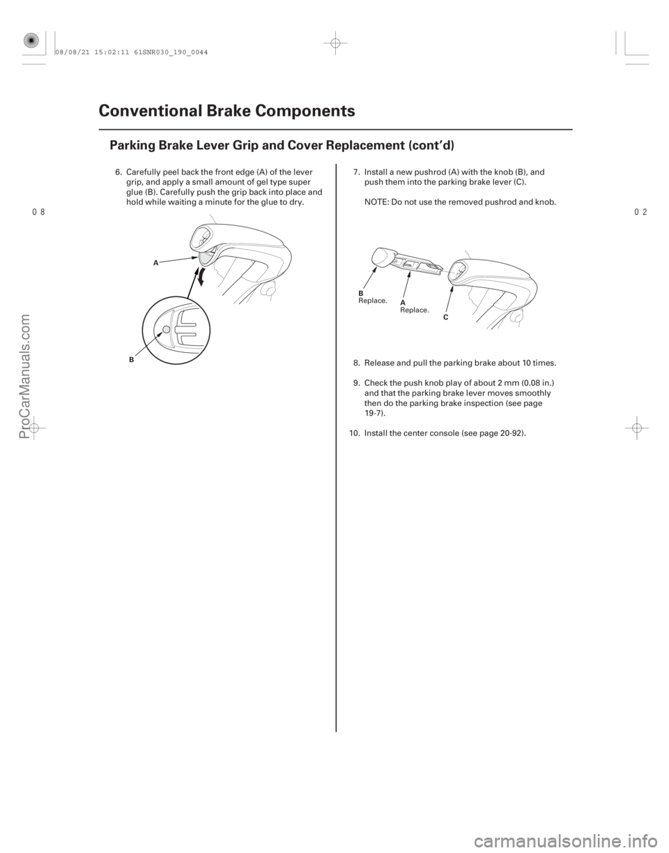
Parking Brake Lever Grip and Cover Replacement (cont’d)
A
B C
B
A
6. Carefully peel back the front edge (A) of the levergrip, and apply a small amount of gel type super
glue (B). Carefully push the grip back into place and
hold while waiting a minute for the glue to dry. 7. Install a new pushrod (A) with the knob (B), and
push them into the parking brake lever (C).
NOTE: Do not use the removed pushrod and knob.
8. Release and pull the parking brake about 10 times.
9. Check the push knob play of about 2 mm (0.08 in.) and that the parking brake lever moves smoothly
then do the parking brake inspection (see page
19-7).
10. Install the center console (see page 20-92).
Replace. Replace.
08/08/21 15:02:11 61SNR030_190_0044
ProCarManuals.com
DYNOMITE -2009-
Page 1661 of 2893
���� ���
�(�#����������������
�����������������������)���
19-16919-169
Yaw Rate-Lateral Acceleration
Sensor Replacement VSA Sensor Neutral Position")
���
�(�#�'���������������
�������������
�
� �����)���� ���
�(�#�'���������������
�����������������������)���
19-16919-169
Yaw Rate-Lateral Acceleration
Sensor Replacement VSA Sensor Neutral Position
Memorization
AB
9.8 N·m
(1.0 kgf·m, 7.2 lbf·ft) A
NOTE:
Do not damage or drop the sensor as it is sensitive.
Do not use power tools when replacing the sensor.
1. Turn the ignition switch to LOCK (0).
2. Remove the center console (see page 20-92).
3. Remove the yaw rate-lateral acceleration sensor (A) mounting bolts.
4. Pull out the yaw rate-lateral acceleration sensor, then disconnect the sensor connector (B).
5. Install the yaw rate-lateral acceleration sensor in the reverse order of removal.
6. Do the VSA sensor neutral position memorization (see page 19-169). NOTE: Do not press the brake pedal during this
procedure.
1. Park the vehicle on a flat and level surface, with the steering wheel in the straight ahead position.
2. With the ignition switch in LOCK (0), connect the HDS to the data link connector (DLC) (A) under the
driver’s side of the dashboard.
3. Turn the ignition switch to ON (II).
4. Make sure the HDS communicates with the vehicle and the VSA modulator-control unit. If it doesn’t
troubleshoot the DLC circuit (see page 11-204).
5. Select VSA ADJUSTMENT with the HDS, and follow the screen prompts.
NOTE: See the HDS Help menu for specific
instructions.
6. Turn the ignition switch to LOCK (0).
08/08/21 15:06:46 61SNR030_190_0169
ProCarManuals.com
DYNOMITE -2009-