Page 2395 of 2893

Navigation Unit Connector A (17P) TerminalNumber Wire Color Terminal Name Description Voltage (about) Symptom
23-113")
�µ
�´�µ
�´ �´
��
��Navigation Unit Inputs and Outputs for Connector A (17P)
Navigation Unit Connector A (17P) TerminalNumber Wire Color Terminal Name Description Voltage (about) Symptom
23-113
1 RED ILL ( )
Ground for
illumination light With full dash
lights brightness,
0VIf open: When brightness = Auto, night mode for the
display is inoperative when lights on.
If short to ground: No change to display.
9 BLK RADIO GND (Ground)Ground for display
unit 0 V
If open: No change to display.
If short to ground: No change to display.
10 GRY ILL ( ) (Illumination
positive)Parking light on
signal from dash
and console lights Light on =
battery voltage,
Lights off = 0 VIf open: When brightness = Auto, night mode for the
display is inoperative when lights on.
If short to ground: Blows fuse No. 14 (7.5 A) in
under-dash fuse/relay box.
13 BLU VSP (Vehicle speed
pulse)Vehicle speed
pulse signal from
ECM/PCM Pulses 0 5 V:
Average 2.5 V,
when movingIf open: No vehicle speed pulses.
Diagnostic screen Car Status, VSP Navi = 0.
If short to ground: No vehicle speed pulses.
Diagnostic screen Car Status, VSP Navi = 0.
17 WHT B ( B power
source)Continuous power
source
Battery voltage If open: Screen completely off (no backlight visible).
If short to ground: Blows fuse No. 23 (10 A) in the
under-hood fuse/relay box.
(cont’d)
Wire side of female terminals
08/08/21 14:06:30 61SNR030_230_0116
ProCarManuals.com
DYNOMITE -2009-
Page 2396 of 2893

Navigation Unit Connector C (12P)TerminalNumber Wire Color Terminal Name Description Voltage (about) Symptom
23-114Navigation Sys")
�´�µ
��
�
Navigation Unit Inputs and Outputs for Connector C (12P)
Navigation Unit Connector C (12P)TerminalNumber Wire Color Terminal Name Description Voltage (about) Symptom
23-114Navigation System
System Description (cont’d)
1 WHT B BACK UP Continuous power
sourceBattery voltage If open: Display picture goes out (display back light
still on). NOTE: System will reboot to enter code
screen.
If short to ground: Blows fuse No. 23 (10 A) in the
under-dash fuse/relay box.
4 BLK GND Ground for navigation unit0 V If open: No effect on system.
If short to ground: No effect on system.
7 BRN BACK LT Reverse signal of select laver from
Multiplex
integrated Control
unit (A/T) or
backup light switch
(M/T)In reverse,
battery voltage:
Otherwise0V
If open: Navigation never sees the reverse signal
and back-up camera does not come on when in
reverse. Diagnostic screen Car Status, Back = 0.
If short to ground: Blows fuse No. 10 (7.5 A) in the
under-dash fuse/relay box.
Wire side of female terminals
08/08/21 14:06:30 61SNR030_230_0117
ProCarManuals.com
DYNOMITE -2009-
Page 2397 of 2893

Navigation Unit Connector D (5P) TerminalNumber Wire Color Terminal Name Description Voltage (about) Symptom
23-115
1 BRN MI")
�´�µ�µ�µ
��
��Navigation Unit Inputs and Outputs for Connector D (5P)
Navigation Unit Connector D (5P) TerminalNumber Wire Color Terminal Name Description Voltage (about) Symptom
23-115
1 BRN MIC GND Ground for
microphone signal0 V If open: No microphone signal shown in
diagnostics: Navi System Link and Functional Set
up Mic Level.
If short to ground: No effect on voice recognition.
2 YEL MIC SIG Microphone output signal positive45V(with
navigation TALK
button pressed)If open: No microphone signal shown in diagnostic
screens: Navi System Link and Functional Setup
Mic Level.
If short to ground: No microphone signal shown in
diagnostic screens: Navi System Link and
Functional Setup Mic Level.
3 GRY MIC SH Shield for terminal No.1,2,50 V If open: No effect on voice recognition.
If short to ground: No effect on voice recognition.
4 GRN NAVI GUIDE Steering wheel switch output45V
(navigation TALK
button pressed)
2.5 3 V
(navigation
BACK button
pressed)If open: Steering wheel navigation TALK, and
navigation BACK buttons do not work.
If short to ground: Steering wheel navigation TALK,
and navigation BACK buttons do not work.
5 ORN MIC ADPT Control signal for microphone0 V If open: No effect on voice recognition.
If short to ground: No effect on voice recognition.
: The shielded wires have a heat-shrunk tube insulating the outside of the wire. The color of the insulating tube, typically black or dark gray, may not match the color of the wire listed on the schematic.
(cont’d)
Wire side of female terminals
08/08/21 14:06:30 61SNR030_230_0118
ProCarManuals.com
DYNOMITE -2009-
Page 2398 of 2893
��
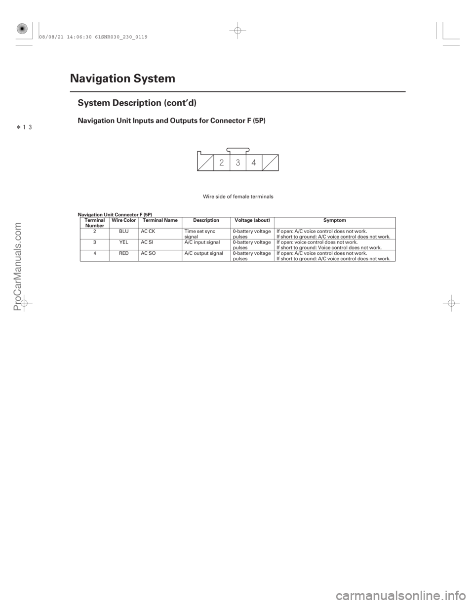
��Navigation Unit Inputs and Outputs for Connector F (5P)
Navigation Unit Connector F (5P)TerminalNumber Wire Color Terminal Name Description Voltage (about) Symptom
23-116Navigation System
System Description (cont’d)
2 BLU AC CK
Time set sync
signal 0-battery voltage
pulsesIf open: A/C voice control does not work.
If short to ground: A/C voice control does not work.
3 YEL AC SI A/C input signal 0-battery voltage
pulsesIf open: voice control does not work.
If short to ground: Voice control does not work.
4 RED AC SO A/C output signal 0-battery voltage
pulsesIf open: A/C voice control does not work.
If short to ground: A/C voice control does not work.
Wire side of female terminals
08/08/21 14:06:30 61SNR030_230_0119
ProCarManuals.com
DYNOMITE -2009-
Page 2399 of 2893
�•�•�•
�•�•�•
��
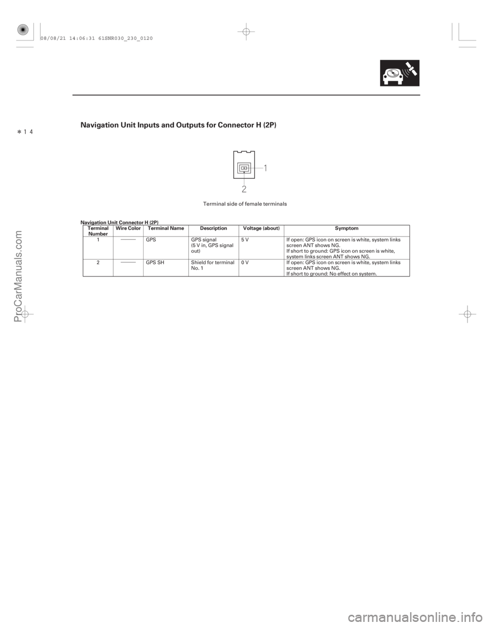
��Navigation Unit Inputs and Outputs for Connector H (2P)
Navigation Unit Connector H (2P)TerminalNumber Wire Color Terminal Name Description Voltage (about) Symptom
23-117
1
GPSGPS signal
(5 V in, GPS signal
out) 5 V
If open: GPS icon on screen is white, system links
screen ANT shows NG.
If short to ground: GPS icon on screen is white,
system links screen ANT shows NG.
2 GPS SHShield for terminal
No. 1 0 V
If open: GPS icon on screen is white, system links
screen ANT shows NG.
If short to ground: No effect on system.
Terminal side of female terminals
08/08/21 14:06:31 61SNR030_230_0120
ProCarManuals.com
DYNOMITE -2009-
Page 2400 of 2893
����
�´
�µ
�´
�´
�µ
�´
�´
�´
�µ
�´
�µ
23-118 Navigation System
Circuit Diagram
AC CK AC SO AC SI
BLU
BACK-UP LIGHT SWITCH (MT)
K-LINE
M")
���
�(�#�'�����#���������
�����������������������)����
�´
�µ
�´
�´
�µ
�´
�´
�´
�µ
�´
�µ
23-118 Navigation System
Circuit Diagram
AC CK AC SO AC SI
BLU
BACK-UP LIGHT SWITCH (MT)
K-LINE
MICU
A14
PUR
Q14 Q4
GRNA4 A6
LT BLU
Q8 Q1
WHT
UNDER-DASH FUSE/RELAY BOX
ORN
BRN10
BRN
3 CABLE REEL
B6 D5 ORN 3
A29
2 1
D4 CABLE REEL GRN
RED/BLK
BACKTALK
5
GRY
GRY*
D3 BRN
D1
D2
YEL
GPS
H1
H2 G504
GND
C4
BLK
VSP
BLU
A13
ILL
ILL
F2 F4
RED YEL F3A1
A10
GRY
RED A17
C1 C7
BRN NAVIGATION UNIT
VOICE CONTROL SWITCH
8
GRN 680
10 k
2.2 k
ECM/PCM
(VEHICLE
SPEED SIGNAL)
GPS SH
GND GPS
ANTENNA
MIC SH
GND MIC
GND
MIC
SIG
NA VI
GUIDE
No. 23 (10 A)
FUSE (In the
under-hood
fuse/relay box)
MIC
ADPT
DASH LIGHTS
BRIGHTNESS
CONTROLLER
No. 14 (7.5 A) FUSE
(In the under-dash
fuse/relay box)
No.14(7.5A)FUSE
(In the under-dash
fuse/relay box)
DASH LIGHTS
BRIGHTNESS
CONTROLLER
B
BACK UP BACK
LT
No. 35
(7.5 A)
FUSE B
RADIO
SCTY
RADIO
ACC
RADIO
AUDIO
REMOTE
GND
MULTIPLEX INTEGRATED
CONTROL UNIT (MICU) (AT)
CLIMATE
CONTROL
UNIT G505
RADIO
GND
A9
BLK VSP
GPS
MIC
GND MIC
SIG
MIC
ADPT
E3
BLU
PNK
E9
BUS SH
GND
XM RECEIVER BRN*
BRN*E10
A9
A10
A3
(’08 model) BUS
(GA-NET)
BUS
(GA-NET)
AUDIO
REMOTE
SWITCHBRN
1
2
5
MICROPHONE *1:
: Shielding
This shielded wires have a heat-shrunk tube
insulating the outside of the wire. The color
of the insulating tube, typically black or dark gray,
may not match the color of the wire listed on the
schematic.
G2
BUS SH
GND BUS
(GA-NET)
BUS
(GA-NET) WHT WHT
4
08/08/21 14:07:25 61SNR030_230_0121
ProCarManuals.com
DYNOMITE -2009-
Page 2401 of 2893
����
�´
�µ
�µ
�µ
�µ �µ
�µ
�µ
�µ
No picture is displayed
YES
NO
YES
NO YES
NO
YES
NO
23-119
Symptom Troubleshooting
NAVIGATION UNI")
����
�����
�(�#�'�����#���������
�����������������������)����
�´
�µ
�µ
�µ
�µ �µ
�µ
�µ
�µ
No picture is displayed
YES
NO
YES
NO YES
NO
YES
NO
23-119
Symptom Troubleshooting
NAVIGATION UNIT CONNECTOR A (17P)
BBACKUP(WHT)
NAVIGATION UNIT CONNECTOR A (17P) ACC RADIO (PUR)
NOTE: Check the vehicle battery condition first.
Make sure that the correct DVD color and version are installed.
Check any official Honda service website for more service information about the navigation system.
Check the connectors for poor connections or loose terminals.
Before troubleshooting, make sure you have the navigation system anti-theft code.
1. Check the No. 23 (10 A) fuse in the under-hood fuse/relay box and No. 35 (7.5 A) fuse in the under-
dash fuse/relay box, and reinstall the fuse if it is OK.
Go to step 2.
Replace the fuse and recheck.
2. Turn the ignition switch to ON (II).
3. Operate the radio and listen to the audio.
Go to step 4.
Refer to audio system troubleshooting.
4. Turn the ignition switch to LOCK (0).
5. Remove the navigation unit (see page 23-155). 6. Measure the voltage between navigation unit
connector A (17P) terminal No. 17 and body ground.
Go to step 7.
Repair open in the wire between the under-
dash fuse/relay box and the navigation unit.
7. Turn the ignition switch to ON (II).
8. Measure the voltage between navigation unit connector A (17P) terminal No. 14 and body ground.
Go to step 9.
Repair open in the wire between the under-
dash fuse/relay box and the navigation unit.
(cont’d)
Wire side of female terminals
Wire side of female terminals
IsthefuseOK? Can y ou hear t he aud i o? Is there battery voltage?
Is there battery voltage?
08/08/21 14:07:25 61SNR030_230_0122
ProCarManuals.com
DYNOMITE -2009-
Page 2402 of 2893
�
��
�µ
�µ �µ
�µ
�µ
�µ
�µ
�µ
YES
NO YES
NO
YES
NO
YES
NO
Picture has lines/rolls/other issues or is an
odd color
23-12023-120Navig")
�����
�����
�(�#�'�����#���������
�����������������������)�
��
�µ
�µ �µ
�µ
�µ
�µ
�µ
�µ
YES
NO YES
NO
YES
NO
YES
NO
Picture has lines/rolls/other issues or is an
odd color
23-12023-120Navigation System
Symptom Troubleshooting (cont’d)
NAVIGATION UNIT CONNECTOR A (17P)
RADIO GND
(BLK)
NAVIGATION UNIT CONNECTOR C (12P) GND (BLK)
9. Measure the voltage between navigation unitconnector A (17P) terminal No. 9 and body ground,
and between navigation unit connector C (12P)
terminal No. 4 and body ground.
Replace the navigation unit (see page 23-155).
Repair open in the wire between the
navigation unit and body ground (G 504) (see page
22-30), (G505) (see page 22-32). NOTE:
Check the vehicle battery condition first.
Make sure that the correct DVD color and version are installed.
Check any official Honda service website for more service information about the navigation system.
Check the navigation screen settings for brightness, contrast, black level and the color screen for map
color and menu color.
Check the connectors for poor connections or loose terminals.
Before troubleshooting, make sure you have the navigation and audio system anti-theft codes.
1. Check for electronic aftermarket accessories (possibly hidden) mounted near the navigation unit.
Disable the accessories, and recheck.
Go to step 2.
2. Turn the ignition switch to ON (II).
3. Start up the navigation picture.
Go to step 5.
Go to step 4.
4. Go into the Diagnostic mode and use RGB Color diagnostic under Monitor Check (see page 23- 137).
Go to step 5.
Replace the navigation unit (see page 23-155).
Wire side of female terminals
Wire side of female terminals
Is t her e l ess t han 0.1 V ? Ar e t her e any el ect r oni c accessor i es?
Is the picture scrolling horizontally (lef t to right orright to left)?
Ar e t he r ed , gr een, and bl ue col or ed ci r cl e show n?
08/08/21 14:07:26 61SNR030_230_0123
ProCarManuals.com
DYNOMITE -2009-