Page 271 of 2893
: 0.060 0.120 mm
(0.0024 0.0047 in.)
Service Limit: 0.15 mm (0.006 in.)
8-20 Engine Lubrication
Oil Pump Overhaul (cont’d)
6x1.")
������
��
�
��
�´
�µ
�µ
No. 2 Journal Oil Clearance
Standard (New): 0.060 0.120 mm
(0.0024 0.0047 in.)
Service Limit: 0.15 mm (0.006 in.)
8-20 Engine Lubrication
Oil Pump Overhaul (cont’d)
6x1.0mm
12 N·m
(1.2 kgf·m, 8.7 lbf·ft)
K20Z2 engine:
8x1.25mm
27 N·m
(2.8 kgf·m, 20 lbf·ft)
K20Z3 engine:
8x1.25mm
28 N·m
(2.9 kgf·m, 21 lbf·ft)
16 °
7. Clean both balancer shaft No. 2 journals and the
bearing halves with a clean shop towel, then install
the balancer shafts into the lower balancer shaft
holder.
8. Place one strip of plastigage across each No. 2 journal.
9. Reinstall the bearings and the upper balancer shaft holder, then tighten the bolts.
NOTE: Do not rotate the balancer shafts during inspection.
After torquing, tighten the three 8 mm bolts extra 16 ° (K20Z3 engine). 10. Remove the upper balancer shaft holder and the
bearings again, and measure the widest part with
the plastigage. If the balancer shaft No. 2 journal oil
clearance is out-of-tolerance, install new bearings,
and recheck. If it is still out-of-tolerance, replace the
balancer shafts.
11. Align the punch mark on the rear balancer shaft in the center of the two punch marks on the front
balancer shaft, then install the balancer shafts on
the lower balancer shaft holder.
08/08/21 14:36:49 61SNR030_080_0020
ProCarManuals.com
DYNOMITE -2009-
Page 272 of 2893
������
�� ����
���
�´
Oil Pump Installation
8-21
B
C
6x1.0mm
12 N·m
(1.2 kgf·m, 8.7 lbf·ft) A
K20Z2 engine:
8x1.25mm
27 N·m
(2.8 kgf·m, 20 lbf·ft)
K20Z3 engine:
8x1.25mm
28 N·m
(2.9 kgf·m, 21 lbf·ft)
16 °
6x1.0mm
12 N·m
(1.2 kgf·m, 8.7 lbf·ft) A
B
B A
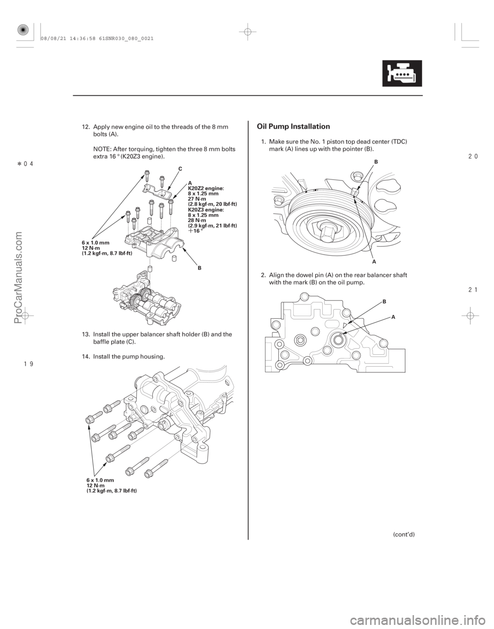
12. Apply new engine oil to the threads of the 8 mm bolts (A).
NOTE: After torquing, tighten the three 8 mm bolts
extra 16 ° (K20Z3 engine).
13. Install the upper balancer shaft holder (B) and the baffle plate (C).
14. Install the pump housing. 1. Make sure the No. 1 piston top dead center (TDC)
mark (A) lines up with the pointer (B).
2. Align the dowel pin (A) on the rear balancer shaft with the mark (B) on the oil pump.
(cont’d)
08/08/21 14:36:58 61SNR030_080_0021
ProCarManuals.com
DYNOMITE -2009-
Page 273 of 2893

A
8x1.25mm
22N·m(2.2kgf·m,16lbf·ft) 8x1.25mm
22 N·m
(2.2 kgf·m, 16 lbf·ft)A
10x1.25mm
44 N·m
(4.5 kgf·m, 33 lbf·ft)
10x1")
����
��������
����
8-22Engine Lubrication
Oil Pump Overhaul (cont’d)
A
8x1.25mm
22N·m(2.2kgf·m,16lbf·ft) 8x1.25mm
22 N·m
(2.2 kgf·m, 16 lbf·ft)A
10x1.25mm
44 N·m
(4.5 kgf·m, 33 lbf·ft)
10x1.25mm
44 N·m
(4.5 kgf·m, 33 lbf·ft) B
C
D B
A
6x1.0mm
12 N·m
(1.2 kgf·m, 8.7 lbf·ft)
3. To hold the rear balancer shaft, insert a 6 mm long pin punch (Snap-on PPC 108LA or equivalent) (A)
into the maintenance hole in the lower balancer
shaft holder and through the rear balancer shaft.
4. Apply new engine oil to the threads of the oil pump sprocket mounting bolt (A).
5. Loosely install the oil pump (B), then install the oil pump sprocket (C).
6. Tighten the oil pump mounting bolts and the oil pump sprocket mounting bolt.
7. Remove the 6 mm long pin punch (D). 8. Squeeze the new oil pump chain tensioner (A), then
install the set clip (B) on it as shown.
NOTE: The set clip is supplied with the oil pump
chain tensioner.
9. Install the new oil pump chain tensioner.
08/08/21 14:36:59 61SNR030_080_0022
ProCarManuals.com
DYNOMITE -2009-
Page 274 of 2893
����
8-23
10. Remove the set clip from the oil pump chaintensioner.
11. Install the oil pan (see page 7-29).
08/08/21 14:36:59 61SNR030_080_0023
ProCarManuals.com
DYNOMITE -2009-
Page 286 of 2893
���
���
����
�(�#�'�����������
�������������������
� �����)����
9-11
Exhaust Manifold Removal and Installation
A B
A
B
1. Relieve the fuel pressure (see page 11-322).
2. Loosen the drain plug in the radiator, and drain the
engine coolant (see page 10-8).
3. Remove the under-cowl panel (see step 4 on page 20-164).
4. Disconnect the evaporative emission (EVAP) canister hose (A) and the brake booster vacuum
hose (B).
5. Remove the quick-connect fitting cover (A), then disconnect the fuel feed hose (B) (see page 11-329). 6. Disconnect the heater hoses.
7. Remove the rocker arm oil control valve (see page
11-296).
8. Remove the intermediate shaft heat shield (see step 3 on page 16-23).
(cont’d)
08/08/21 14:37:37 61SNR030_090_0011
ProCarManuals.com
DYNOMITE -2009-
Page 292 of 2893
����
�(�#�'�����������
���������������������������)���
K20Z3 engine
10-3
THERMOSTAT
RADIATOR
ENGINE COOLANT TEMPERATURE
(ECT) SENSOR 2
WATER PUMP
A/C CONDENSER FAN ASSEMBLY RADIATOR FAN ASSEMBLY WATER OUTLET
COOLANT SEPARATOR
OIL COOLER
WATER PASSAGE
Test, page 10-5
Replacement, page 10-10
Replacement, page 10-19
Inspection, page 10-6
Replacement, page 10-6
Replacement, page 10-19
Fan Motor Test, page 10-5 Replacement, page 10-19
Fan Motor Test, page 10-5 Replacement, page 10-16
Replacement, page 10-11
08/08/21 14:39:56 61SNR030_100_0003
ProCarManuals.com
DYNOMITE -2009-
Page 293 of 2893
���
�µ
�µ�µ ���
�(�#������������
�������������������
�������)����
10-410-4 Cooling System
Radiator Cap Test
Radiator Test
A
B
A
1. W")
�µ
�µ�µ
���
�(�#�'�����������
�������������������
�������)���
�µ
�µ�µ ���
�(�#�'�����������
�������������������
�������)����
10-410-4 Cooling System
Radiator Cap Test
Radiator Test
A
B
A
1. Wait until the engine is cool, then carefully removethe radiator cap (A). Wet the radiator cap seal with
engine coolant, then install it on a commercially
available pressure tester (B).
2. Apply a pressure of 93 123 kPa (0.95 1.25 kgf/cm , 14 18 psi).
3. Check for a drop in pressure.
4. If the pressure drops, replace the cap. 1. Wait until the engine is cool, then carefully remove
the radiator cap and fill the radiator with engine
coolant to the base of the filler neck.
2. Attach a commercially available pressure tester (A) to the radiator, and apply a pressure of 93 123 kPa
(0.95 1.25 kgf/cm , 14 18 psi).
3. Inspect for engine coolant leaks and a drop in pressure.
4. Check for engine oil in the coolant and/or coolant in the engine oil.
5. Remove the tester, and reinstall the radiator cap.
2 2
08/08/21 14:39:57 61SNR030_100_0004
ProCarManuals.com
DYNOMITE -2009-
Page 296 of 2893
���
���
�(�#������������
�����������
�������
�\"�����)����
K20Z3 engine
10-710-7
Coolant Check
A B
C
6x1.0mm
12 N·m
(1.2 kgf·m, 8.7 lbf·ft) C A
B")
���
�(�#�'�����������
���������������
���
� �����)���
���
�(�#�'�����������
�����������
�������
�"�����)����
K20Z3 engine
10-710-7
Coolant Check
A B
C
6x1.0mm
12 N·m
(1.2 kgf·m, 8.7 lbf·ft) C A
B
1. Remove the drive belt (see page 4-31).
2. Drain the engine coolant (see page 10-8).
3. Remove the drive belt auto-tensioner pulley (see page 4-33).
4. Remove the crankshaft pulley (see page 6-16).
5. Remove the oil cooler joint pipe (A), then remove the seven bolts securing the water pump. Remove
the water pump (B).
6. Inspect, and clean the O-ring groove and mating surface of the water passage.
7. Install the water pump with new O-rings (C) and the oil cooler joint pipe.
8. Clean up any spilled engine coolant.
9. Install the crankshaft pulley (see page 6-17).
10. Install the drive belt auto-tensioner pulley (see page 4-33).
11. Install the drive belt (see page 4-31).
12. Refill the radiator with engine coolant, and bleed the air from the cooling system with the heater
valve open (see step 6 on page 10-8). 1. Check the coolant level in the coolant reservoir.
Make sure it is between the MAX mark (A) and MIN
mark (B).
2. If the coolant level in the coolant reservoir is at or below the MIN mark, add coolant to bring it up to
the MAX mark, then inspect the cooling system for
leaks.
08/08/21 14:39:58 61SNR030_100_0007
ProCarManuals.com
DYNOMITE -2009-