Page 244 of 2893

7-28Engine Block
Crankshaft Installation (cont’d)
0.2 1.2 mm
(0.001 0.047 in.)
BA
6x1.0mm
12 N·m
(1.2 kgf·m, 8.7 lbf")
����
�
���µ�µ
�µ
�µ
Oil Seal Installed Height: 0.2 1.2 mm
(0.001 0.047 in.)
7-28Engine Block
Crankshaft Installation (cont’d)
0.2 1.2 mm
(0.001 0.047 in.)
BA
6x1.0mm
12 N·m
(1.2 kgf·m, 8.7 lbf·ft)
25. Measure the distance between the engine block (A) and the crankshaft oil seal (B).
26. Install the baffle plates. 27. Install the oil pump (see page 8-21).
28. Install the oil pan (see page 7-29).
29. Install the cylinder head (see page 6-62).
30. M/T model: Install the flywheel (see page 12-21),
the clutch disc (see page 12-23), and the pressure
plate (see page 12-23).
31. A/T model: Install the drive plate (see page 14-242).
32. Install the transmission: Manual transmission (see page 13-14)
Automatic transmission (see page 14-242)
33. Install the engine assembly (see page 5-13). NOTE: Whenever any crankshaft or connecting rod
bearing is replaced, it is necessary after
reassembly to run the engine at idle speed until it
reaches normal operating temperature, then
continue to running it for about 15 minutes.
08/08/21 14:33:10 61SNR030_070_0028
ProCarManuals.com
DYNOMITE -2009-
Page 245 of 2893
����
7-29
Oil Pan Installation
6x1.0mm
12 N·m
(1.2 kgf·m, 8.7 lbf·ft)
1. Remove all of the old liquid gasket from the oil pan mating surf")
���
����
����
�(�#�'�����������
�������������������
� �����)����
7-29
Oil Pan Installation
6x1.0mm
12 N·m
(1.2 kgf·m, 8.7 lbf·ft)
1. Remove all of the old liquid gasket from the oil pan mating surfaces, the bolts, and the bolt holes.
2. Clean, and dry the oil pan mating surfaces.
3. Apply liquid gasket, P/N 08717-0004, 08718-0001, 08718-0003, or 08718-0009, evenly to the lower
engine block mating surface, and to the inside edge
of the threaded bolt holes. Install the component
within 5 minutes of applying the liquid gasket.
NOTE: If you apply liquid gasket P/N 08718-0012, the component must be install within 4 minutes.
If too much time has passed after applying the liquid gasket, remove the old liquid gasket and
residue, then reapply new liquid gasket.
4. Install the oil pan. 5. Tighten the bolts/nuts in three steps. In the final
step, tighten all bolts/nuts, in sequence, to 12 N·m
(1.2 kgf·m, 8.7 lbf·ft). Wipe off the excess liquid
gasket on the each side of crankshaft pulley and the
flywheel/drive plate.
NOTE: Wait at least 30 minutes before filling the engine with oil.
Do not run the engine for at least 3 hours after installing the oil pan.
6. K20Z2 engine: Install the torque converter cover/ clutch cover.
(cont’d)
Apply liquid gasket
along the broken line.
08/08/21 14:33:11 61SNR030_070_0029
ProCarManuals.com
DYNOMITE -2009-
Page 246 of 2893

B
6x1.0mm
12 N·m
(1.2 kgf·m, 8.7 lbf·ft)
A
12x1.25mm
64N·m(6.5kgf·m,47lbf·ft)
6x1.0mm
12 N·m
(1.2 kgf·m, 8.7 lbf·ft) 12 x 1.25 m")
���
��������
7-30Engine Block
Oil Pan Installation (cont’d)
B
6x1.0mm
12 N·m
(1.2 kgf·m, 8.7 lbf·ft)
A
12x1.25mm
64N·m(6.5kgf·m,47lbf·ft)
6x1.0mm
12 N·m
(1.2 kgf·m, 8.7 lbf·ft) 12 x 1.25 mm
74 N·m
(7.5 kgf·m, 54 lbf·ft)
7. K20Z3 engine: Install the transmission mounting
bolts (A) and the clutch cover (B).
8. A/T model: Install the shift cable cover. 9. Install the lower torque rod bracket.
10. If the engine is still in the vehicle, do the following steps.
11. Attach the front subframe adapter (VSB02C000016) to the front subframe, and hang the belt of the front
subframe adapter over the front of the subframe.
Secure the belt with its stop, then tighten the wing
nut (see step 53 on page 5-9).
12. Line up the slots in the front subframe adapter arms with the bolt holes on the jack base, then
securely attach them with four bolts. Lift the front
subframe up to the body.
13. Loosely install the new front subframe mounting bolts (see step 17 on page 5-17).
14. Align all reference marks on the front subframe with the edges of the body, then tighten the bolts
on the front subframe to the specified torque (see
step 18 on page 5-18).
15. Remove the jack and the front subframe adapter.
16. Tighten the new mid-stiffener mounting bolts on both sides (see step 20 on page 5-18).
17. Lower the vehicle on the lift.
18. Loosen the upper torque rod mounting bolt (see step 5 on page 5-15).
Replace.
08/08/21 14:33:12 61SNR030_070_0030
ProCarManuals.com
DYNOMITE -2009-
Page 247 of 2893

19. Raise the vehicle on the lift.
20. Install the lower torque rod, then tighten the newlower torque rod mounting bolts in the numbered
sequence sh")
����
7-31
6x1.0mm
12 N·m
(1.2 kgf·m, 8.7 lbf·ft)
19. Raise the vehicle on the lift.
20. Install the lower torque rod, then tighten the newlower torque rod mounting bolts in the numbered
sequence shown (see step 21 on page 5-18).
21. M/T model: Loosely tighten the new front mount mounting bolt (see step 22 on page 5-19).
22. Lower the vehicle on the lift.
23. Remove the engine support hanger and engine hanger adapter.
24. Tighten the upper torque rod mounting bolt (see step 25 on page 5-19).
25. Raise the vehicle on the lift.
26. M/T model: Tighten the front mount mounting bolt (see step 27 on page 5-19).
27. A/T model: Install the bolt securing the automatic transmission fluid (ATF) filter. 28. Install the stiffener, then tighten the steering
gearbox mounting bolt and the stiffener mounting
bolt. Install the harness clamp to the front subframe
(see step 29 on page 5-20).
29. Install the steering gearbox bracket. Install the stiffener, then tighten the steering gearbox
mounting bolt and the stiffener mounting bolt (see
step 32 on page 5-20).
30. Connect the lower arms to the knuckles (see step 9 on page 18-16).
31. Connect the stab ilizer links (see page 18-25).
32. Install the splash shield (see step 40 on page 5-20).
33. Install the front wheels.
34. Refill the engine with engine oil (see step 4 on page 8-10).
08/08/21 14:33:12 61SNR030_070_0031
ProCarManuals.com
DYNOMITE -2009-
Page 248 of 2893
����
�µ �µ
�µ
�µ
Special Tools Required
Oil Seal Installed Height: 0.2 1.2 mm(0.008 0.047 in.)
7-32Engine Block
Transmission End Crankshaf")
���
����
�(�#�'�����������
�����
�����
�����
��� �����)����
�µ �µ
�µ
�µ
Special Tools Required
Oil Seal Installed Height: 0.2 1.2 mm(0.008 0.047 in.)
7-32Engine Block
Transmission End Crankshaft Oil Seal Installation - In Car
07749-0010000
07ZAD-PNAA100 0.2 1.2 mm
(0.008 0.047 in.)
B
A
Driver 07749-0010000
Oil seal driver attachment 96 07ZAD-PNAA100 1. Remove the transmission: Manual transmission (see page 13-7)
Automatic transmission (see page 14-233)
2. M/T model: Remove the pressure plate (see page 12-19), the clutch disc (see page 12-20), and the
flywheel (see page 12-21).
3. A/T model: Remove the drive plate (see page 14-242).
4. Clean, and dry the crankshaft oil seal housing.
5. Apply a light coat of new engine oil around the crankshaft oil seal.
6. Apply a light coat of new engine oil to the crankshaft and to the lip of the crankshaft oil seal.
7. Use the driver and the oil seal driver attachment 96 to drive a new oil seal squarely into the engine
block to the specified installed height. 8. Measure the distance between the engine block (A)
and the crankshaft oil seal (B).
9. M/T model: Install the flywheel (see page 12-21), the clutch disc (see page 12-23), and the pressure
plate (see page 12-23).
10. A/T model: Install the drive plate (see page 14-242).
11. Install the transmission: Manual transmission (see page 13-14)
Automatic transmission (see page 14-242)
08/08/21 14:33:12 61SNR030_070_0032
ProCarManuals.com
DYNOMITE -2009-
Page 251 of 2893
����
Engine Mechanical
Engine Lubrication
................................................................................................................")
�(�#�'�������������������������������
�/�����)����
Engine Mechanical
Engine Lubrication
...................................................................................................................................... ..............
.......................................... .........................................
............................................. ..............................
.......................................................... ................................................................................................................
..............................................
....................................................
......................................................... ......................................................
................................................................
...................................................................... ..............
.......................................... .........................................
............................................. ..............................
.......................................................... ................................................................................................................
..............................................
....................................................
......................................................... ......................................................
Special Tools . 8-2
Component Location Index . 8-3
Symptom Troubleshooting Index . 8-5
Low Oil Pressure Indicator Circuit Diagram . 8-6
Low Oil Pressure Indicator Circuit
Troubleshooting (Open) . 8-7
Low Oil Pressure Indicator Circuit Troubleshooting (Short) . 8-8
Oil Pressure Switch Test . 8-9
Oil Pressure Switch Replacement . 8-9
Oil Pressure Test . 8-10
Engine Oil Replacement . 8-10
Engine Oil Filter Replacement . 8-11
Oil Filter Feed Pipe Replacement . 8-12
Oil Cooler Replacement . 8-13
Oil Jet Replacement . 8-13
Oil Jet Inspection . 8-14
Oil Pump Overhaul . 8-15
08/08/21 14:36:35 61SNR030_080_0001
ProCarManuals.com
DYNOMITE -2009-
Page 252 of 2893
���
�(�#�'�������������������������������
�%�����)����Ref. No. Tool Number Description Qty
8-2
Engine Lubrication
Special Tools
07HAA-PJ70101
Oil Filter Wrench 1
08/08/21 14:36:35 61SNR030_080_0002
ProCarManuals.com
DYNOMITE -2009-
Page 253 of 2893
����
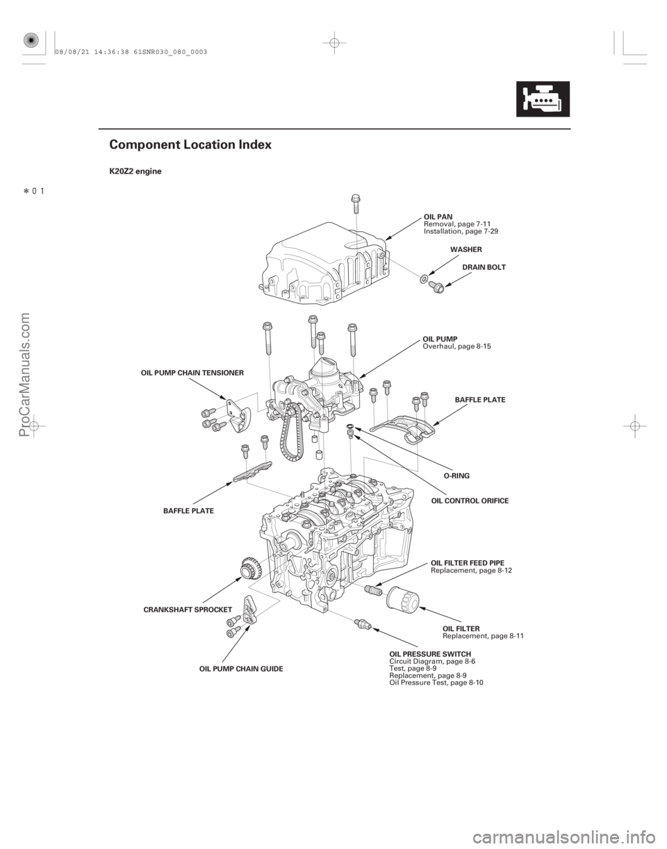
�(�#�'���������������������������������������)���� K20Z2 engine
8-3
Component Location Index
OIL PRESSURE SWITCHOIL FILTER
OIL PUMP
DRAIN BOLT
O-RING
OIL PAN
BAFFLE PLATE
OIL CONTROL ORIFICE
OIL PUMP CHAIN GUIDE
CRANKSHAFT SPROCKET
OIL PUMP CHAIN TENSIONER
BAFFLE PLATE OIL FILTER FEED PIPEWASHER
Circuit Diagram, page 8-6
Test, page 8-9
Replacement, page 8-9
Oil Pressure Test, page 8-10 Replacement, page 8-11
Overhaul, page 8-15
Removal, page 7-11
Installation, page 7-29
Replacement, page 8-12
08/08/21 14:36:38 61SNR030_080_0003
ProCarManuals.com
DYNOMITE -2009-