Page 1964 of 2893
����
21-8321-83
A/C Compressor Replacement
A C
B
6x1.0mm
9.8 N·m
(1.0 kgf·m,
7.2 lbf·ft)
A
B
13. Remove the self-tapping screws, the heater co")
�������
�(�#�'�����������
���
�
���
����������� �����)����
21-8321-83
A/C Compressor Replacement
A C
B
6x1.0mm
9.8 N·m
(1.0 kgf·m,
7.2 lbf·ft)
A
B
13. Remove the self-tapping screws, the heater core cover (A), the grommet (B). and carefully pull out
the heater core (C).
14. Install the heater core and the evaporator core in the reverse order of removal.
15. Install the heater unit in the reverse order of removal, and note these items:
Do not interchange the inlet and outlet heater hoses, and install the hose clamps securely.
Refill the cooling system with engine coolant (see page 10-8).
Make sure that there is no coolant leakage.
Make sure that there is no air leakage.
Refer to evaporator core replacement (see page 21-78).
16. Do the battery terminal reconnection procedure (see page 22-68). NOTE: Do not install an A/C compressor into a system
unless you are completely sure that the system is free
of contamination. Installing the A/C compressor into a
contaminated system can result in premature A/C
compressor failure.
1. If the A/C compressor is marginally operable, run the engine at idle speed, and let the air
conditioning work for a few minutes, then shut the
engine off.
2. Recover the refrigerant with a recovery/recycling/ charging station (see page 21-90).
3. Remove the drive belt (see page 4-31).
4. Remove the front bulkhead and the condenser fan shroud (see page 10-19).
5. Remove the splash shield (see page 20-172).
6. Remove the bolt and the nut, then disconnect the suction hose (A) and discharge hose (B) from the
A/C compressor. Plug or cap the lines immediately
after disconnecting them to avoid moisture and
dust contamination.
(cont’d)
08/08/21 14:43:45 61SNR030_210_0084
ProCarManuals.com
DYNOMITE -2009-
Page 1965 of 2893
����
21-8321-83
A/C Compressor Replacement
A C
B
6x1.0mm
9.8 N·m
(1.0 kgf·m,
7.2 lbf·ft)
A
B
13. Remove the self-tapping screws, the heater co")
�������
�(�#�'�����������
���
�
���
����������� �����)����
21-8321-83
A/C Compressor Replacement
A C
B
6x1.0mm
9.8 N·m
(1.0 kgf·m,
7.2 lbf·ft)
A
B
13. Remove the self-tapping screws, the heater core cover (A), the grommet (B). and carefully pull out
the heater core (C).
14. Install the heater core and the evaporator core in the reverse order of removal.
15. Install the heater unit in the reverse order of removal, and note these items:
Do not interchange the inlet and outlet heater hoses, and install the hose clamps securely.
Refill the cooling system with engine coolant (see page 10-8).
Make sure that there is no coolant leakage.
Make sure that there is no air leakage.
Refer to evaporator core replacement (see page 21-78).
16. Do the battery terminal reconnection procedure (see page 22-68). NOTE: Do not install an A/C compressor into a system
unless you are completely sure that the system is free
of contamination. Installing the A/C compressor into a
contaminated system can result in premature A/C
compressor failure.
1. If the A/C compressor is marginally operable, run the engine at idle speed, and let the air
conditioning work for a few minutes, then shut the
engine off.
2. Recover the refrigerant with a recovery/recycling/ charging station (see page 21-90).
3. Remove the drive belt (see page 4-31).
4. Remove the front bulkhead and the condenser fan shroud (see page 10-19).
5. Remove the splash shield (see page 20-172).
6. Remove the bolt and the nut, then disconnect the suction hose (A) and discharge hose (B) from the
A/C compressor. Plug or cap the lines immediately
after disconnecting them to avoid moisture and
dust contamination.
(cont’d)
08/08/21 14:43:45 61SNR030_210_0084
ProCarManuals.com
DYNOMITE -2009-
Page 2189 of 2893
�����
�����
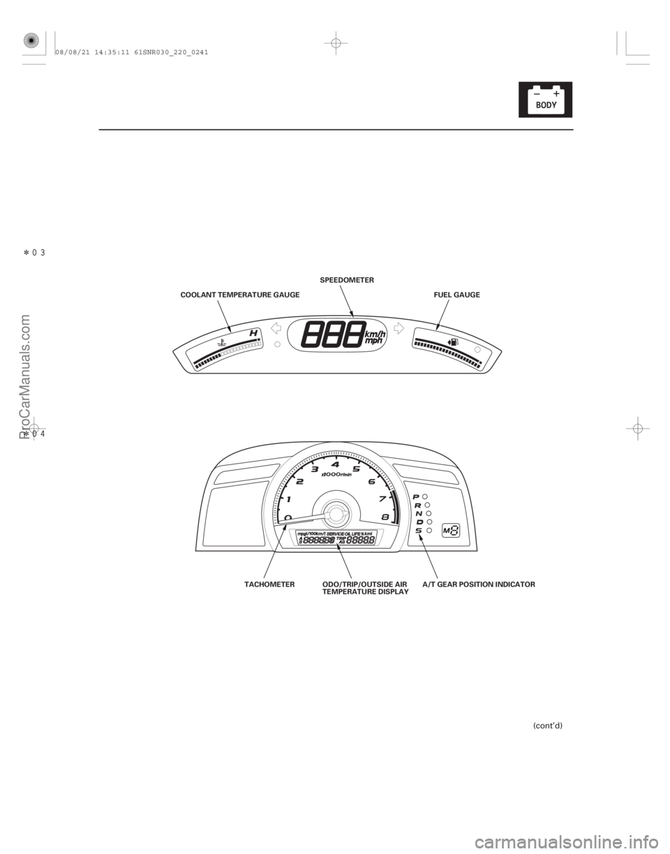
22-239
COOLANT TEMPERATURE GAUGESPEEDOMETER
FUEL GAUGE
TACHOMETER ODO/TRIP/OUTSIDE AIR
TEMPERATURE DISPLAY A/T GEAR POSITION INDICATOR
(cont’d)
08/08/21 14:35:11 61SNR030_220_0241
ProCarManuals.com
DYNOMITE -2009-
Page 2191 of 2893
����
Entering the self-diagnostic function with the HDS
Entering the self-diagnostic function (manual method)
22-241
Self-diagnostic Function
ON (I")
����
�(�#�'���������������
�����������������������)����
Entering the self-diagnostic function with the HDS
Entering the self-diagnostic function (manual method)
22-241
Self-diagnostic Function
ON (II)
OFF ON
OFF ON
Ignition
Switch
Lighting
Switch
SEL/RESET
Switch
5sec.
5sec.
LOCK (0)
Before troubleshooting the gauge system, refer to multiplex integrated control system B-CAN System Diagnosis Test
Mode A (see page 22-93).
The gauge control module (tach) has a self-diagnostic function shown, and also has a customizable reset function.
The beeper drive circuit check.
The indicator drive circuit check.
The switch input test.
The LCD segments check.
The gauges drive circuit check (Tachometer, Fuel gauge, Coolant temperature gauge).
The communication line check (B-CAN, F-CAN, and UART lines).
NOTE: Indicators are also controlled via the communication line.
Using the HDS, select Body Electrical, Gauges, then Function Test and do the self-diagnostic function.
Before doing the self-diagnostic function, check the No. 10 (7.5 A) fuse in the under-dash fuse/relay box and the No. 23
(10 A) fuse in the under-hood fuse/relay box. 1. Push and hold the SEL/RESET switch button.
2. Turn the headlights ON.
3. Turn the ignition switch to ON (II).
4. Within 5 sec., turn the headlights OFF, then ON and OFF again.
5. Within 5 sec., release the SEL/RESET switch button, and then push and release the button three times repeatedly.
NOTE: While in the self-diagnostic mode, the dash lights brightness controller operates normally.
While in the self-diagnostic mode, the SEL/RESET switch button is used to start the Beeper Drive Circuit Test and the Gauge Drive Circuit Check.
If the vehicle speed exceeds 2 km/h (1.2 mph) or the ignition switch is turned to LOCK (0), the self-diagnostic mode ends.
(cont’d)
Move to self-diagnostic mode.
08/08/21 14:35:11 61SNR030_220_0243
ProCarManuals.com
DYNOMITE -2009-
Page 2229 of 2893
����
Description
Outside Air Temperature Indicator Logic Update to the outside air temperature
indicator while driving
Troubleshooting
22-279
Ou")
�µ�µ�µ
�(�#�'���������������������
���������
�������)����
Description
Outside Air Temperature Indicator Logic Update to the outside air temperature
indicator while driving
Troubleshooting
22-279
Outside Air Temperature Indicator Calibration
The outside temperature sensor is located behind the
center of the front bumper. The gauge control module
(tach) uses measurements from this sensor to display
the outside air temperature.
Because of the location of the sensor, it may be affected
by heat reflection from the road, engine and radiator
heat or hot exhaust from surrounding traffic.
These conditions can heat soak the outside air
temperature sensor and cause inaccurate readings.
Logic has been written into the gauge control module
(tach) to help prevent abnormal or fluctuating outside
air temperature indicator readings.
Initial outside air temperature indication after the
ignition switch is turned to ON (II).
If the engine coolant temperature is 60 °C (140 °F) or higher when the ignition switch is turned to ON (II),
the outside air temperature indicated the last time the
key was turned off will be displayed regardless of the
current temperature measured by the outside air
temperature sensor.
If the engine coolant temperature is 59 °C (139 °F) or lower when the ignition switch is turned to ON (II), the
current temperature measured by the outside air
temperature sensor will be indicated. If the temperature measured by the outside air
temperature sensor is greater than the temperature on
the outside air temperature indicator, the outside air
temperature indicator will increase by 1 °C (1.8 °F) per
minute after the vehicle speed is greater than 30 km/h
(19 mph) for more than 1 minute and 30 seconds. It will
continue to increase until the current outside air
temperature is indicated. So, the first change to the
outside air temperature indicator is 1 minute and
30 seconds after the vehicle speed is greater than
30 km/h (19 mph). If the vehicle speed drops below
30 km/h (19 mph), the indicator will not update again
until the vehicle speed is increased to 30 km/h (19 mph)
or more for more than 1 minute and 30 seconds again.
If the outside air temperature is less than the indicated
temperature, the temperature will decrease 1 °C every
2 seconds (1 °F
every 1.1 seconds) until the current
outside air temperature is indicated regardless of
vehicle speed.
If the indicator displays ‘‘ ’’ for more than 2
seconds after selecting the outside air temperature
display mode, check the outside air temperature sensor
(see page 21-68), or gauge control module self-
diagnosis (see page 22-241).
(cont’d)
08/08/21 14:36:00 61SNR030_220_0281
ProCarManuals.com
DYNOMITE -2009-