Page 264 of 2893
���
�(�#�'���������������������������
���
� �����)���
����
�(�#�'�������������������������������
� �����)����
K20Z3 engine K20Z3 engine
8-138-13
Oil Cooler ReplacementOil Jet Replacement
A
D
B
C A
8x0.75mm
16N·m(1.6kgf·m,12lbf·ft)
B
1. Remove the oil filter (see page 8-11).
2. Disconnect the oil cooler bypass hoses (A) and
remove the oil cooler center bolt (B), then remove
the oil cooler (C).
3. Install the oil cooler using a new O-ring (D). Tighten the oil cooler center bolt to 74 N·m (7.5 kgf·m,
54 lbf·ft).
4. Connect the oil cooler bypass hoses.
5. Install the oil filter (see page 8-11). 1. Remove the oil pump (see page 8-16).
2. Remove the baffle plate (see step 8 on page 7-13).
3. Remove the oil jet bolt (A), then remove the oil jet
(B).
4. Carefully install the oil jet, and tighten the oil jet bolt.
5. Install the baffle plate (see step 26 on page 7-28).
6. Install the oil pump (see page 8-21).
08/08/21 14:36:44 61SNR030_080_0013
ProCarManuals.com
DYNOMITE -2009-
Page 265 of 2893
���
�(�#�'�������������������������������
�"�����)���
K20Z3 engine
Torque: 16 N·m (1.6 kgf·m, 12 lbf·ft)
8-14Engine Lubrication
Oil Jet Inspection
1.2 mm (0.05 in.)
1.2 mm
(0.05 in.)
A
B
1. Remove the oil jet, and inspect it as follows. Make sure that a 1.1 mm (0.04 in.) diameter drillwill go through the nozzle hole (A) (1.2 mm
(0.05 in.) diameter).
Insert the other end of a 1.1 mm (0.04 in.) drill into the oil intake (1.2 mm (0.05 in.) diameter).
Make sure the check ball (B) moves smoothly and
has a stroke of approximately 4.0 mm (0.16 in.).
Check the oil jet operation with an air nozzle. It should take at least 200 kPa (2.0 kgf/cm , 28 psi)
to unseat the check ball.
NOTE: Replace the oil jet assembly if the nozzle is
damaged or bent.
2. Carefully install the oil jet. The mounting torque is critical.
2
08/08/21 14:36:45 61SNR030_080_0014
ProCarManuals.com
DYNOMITE -2009-
Page 266 of 2893
����
�(�#�'���������������������������������!�����)����
�´
Exploded View
8-15
Oil Pump Overhaul
6x1.0mm
12 N·m
(1.2 kgf·m, 8.7 lbf·ft)K20Z2 engine:
8x1.25mm
27 N·m
(2.8 kgf·m, 20 lbf·ft)
UPPER BALANCER
SHAFT HOLDER DOWEL PINS
BALANCER SHAFT
BEARINGS
REAR BALANCER
SHAFT
FRONT BALANCER
SHAFT
LOWER BALANCER
SHAFT HOLDER
OUTER ROTOR
INNER ROTOR
RELIEF VALVE
SPRING
SEALING BOLT
39 N·m
(4.0 kgf·m, 29 lbf·ft) OIL PUMP SPROCKET
6x1.0mm
12 N·m
(1.2 kgf·m, 8.7 lbf·ft) 10x1.25mm
44 N·m
(4.5 kgf·m, 33 lbf·ft)
PUMP HOUSING
DOWEL PIN
6x1.0mm
12 N·m
(1.2 kgf·m, 8.7 lbf·ft)
BAFFLE PLATE
K20Z3 engine:
8x1.25mm
28 N·m
(2.9 kgf·m, 21 lbf·ft) 16 °
(cont’d)
Apply new engine oil to
the bolt threads.
The valve must slide freely
in housing bore.
Replace the oil pump
as an assembly if scored.
Apply new engine oil to
the bolt threads.
Apply new engine oil to
the bolt threads.
08/08/21 14:36:45 61SNR030_080_0015
ProCarManuals.com
DYNOMITE -2009-
Page 267 of 2893
����
��������
����
Oil Pump Removal
8-16Engine Lubrication
Oil Pump Overhaul (cont’d)
A
B
A
AB
1. Turn the crankshaft pulley so its top dead center (TDC) mark (A) lines up with the pointer (B).
2. Remove the oil pan (see page 7-11).
3. Remove and discard the oil pump chain tensioner. 4. To hold the rear balancer shaft, insert a 6 mm long
pin punch (Snap-on PPC 108LA or equivalent) (A)
into the maintenance hole in the lower balancer
shaft holder and through the rear balancer shaft.
5. Loosen the oil pump sprocket mounting bolt.
6. Remove the oil pump sprocket (A), then remove the oil pump (B).
08/08/21 14:36:46 61SNR030_080_0016
ProCarManuals.com
DYNOMITE -2009-
Page 269 of 2893
�
�������
�
�
�µ
�µ
�µ �µ
Balancer Shaft Inspection
Balancer Shaft End Play
Front Balancer Shaft:
Standard (New): 0.063 0.108 mm (0.0025 0.0043 in.)
Service Limit: 0.14 mm (0.0055 in.)
Rear Balancer Shaft:
Standard (New): 0.063 0.108 mm (0.0025 0.0043 in.)
Service Limit: 0.14 mm (0.0055 in.)
8-18 Engine Lubrication
Oil Pump Overhaul (cont’d)
A
B
C D
1. Seat the balancer shaft by pushing it away from the
oil pump sprocket end of the oil pump.
2. Zero the dial indicator against the end of the balancer shaft, then push the balancer shaft back
and forth and read the end play. 3. Remove the pump housing.
4. Remove the baffle plate (A) and the upper balancer
shaft holder (with bearings) (B), then remove the
front balancer shaft (C) and the rear balancer
shaft (D).
08/08/21 14:36:48 61SNR030_080_0018
ProCarManuals.com
DYNOMITE -2009-
Page 271 of 2893
: 0.060 0.120 mm
(0.0024 0.0047 in.)
Service Limit: 0.15 mm (0.006 in.)
8-20 Engine Lubrication
Oil Pump Overhaul (cont’d)
6x1.")
������
��
�
��
�´
�µ
�µ
No. 2 Journal Oil Clearance
Standard (New): 0.060 0.120 mm
(0.0024 0.0047 in.)
Service Limit: 0.15 mm (0.006 in.)
8-20 Engine Lubrication
Oil Pump Overhaul (cont’d)
6x1.0mm
12 N·m
(1.2 kgf·m, 8.7 lbf·ft)
K20Z2 engine:
8x1.25mm
27 N·m
(2.8 kgf·m, 20 lbf·ft)
K20Z3 engine:
8x1.25mm
28 N·m
(2.9 kgf·m, 21 lbf·ft)
16 °
7. Clean both balancer shaft No. 2 journals and the
bearing halves with a clean shop towel, then install
the balancer shafts into the lower balancer shaft
holder.
8. Place one strip of plastigage across each No. 2 journal.
9. Reinstall the bearings and the upper balancer shaft holder, then tighten the bolts.
NOTE: Do not rotate the balancer shafts during inspection.
After torquing, tighten the three 8 mm bolts extra 16 ° (K20Z3 engine). 10. Remove the upper balancer shaft holder and the
bearings again, and measure the widest part with
the plastigage. If the balancer shaft No. 2 journal oil
clearance is out-of-tolerance, install new bearings,
and recheck. If it is still out-of-tolerance, replace the
balancer shafts.
11. Align the punch mark on the rear balancer shaft in the center of the two punch marks on the front
balancer shaft, then install the balancer shafts on
the lower balancer shaft holder.
08/08/21 14:36:49 61SNR030_080_0020
ProCarManuals.com
DYNOMITE -2009-
Page 272 of 2893
������
�� ����
���
�´
Oil Pump Installation
8-21
B
C
6x1.0mm
12 N·m
(1.2 kgf·m, 8.7 lbf·ft) A
K20Z2 engine:
8x1.25mm
27 N·m
(2.8 kgf·m, 20 lbf·ft)
K20Z3 engine:
8x1.25mm
28 N·m
(2.9 kgf·m, 21 lbf·ft)
16 °
6x1.0mm
12 N·m
(1.2 kgf·m, 8.7 lbf·ft) A
B
B A
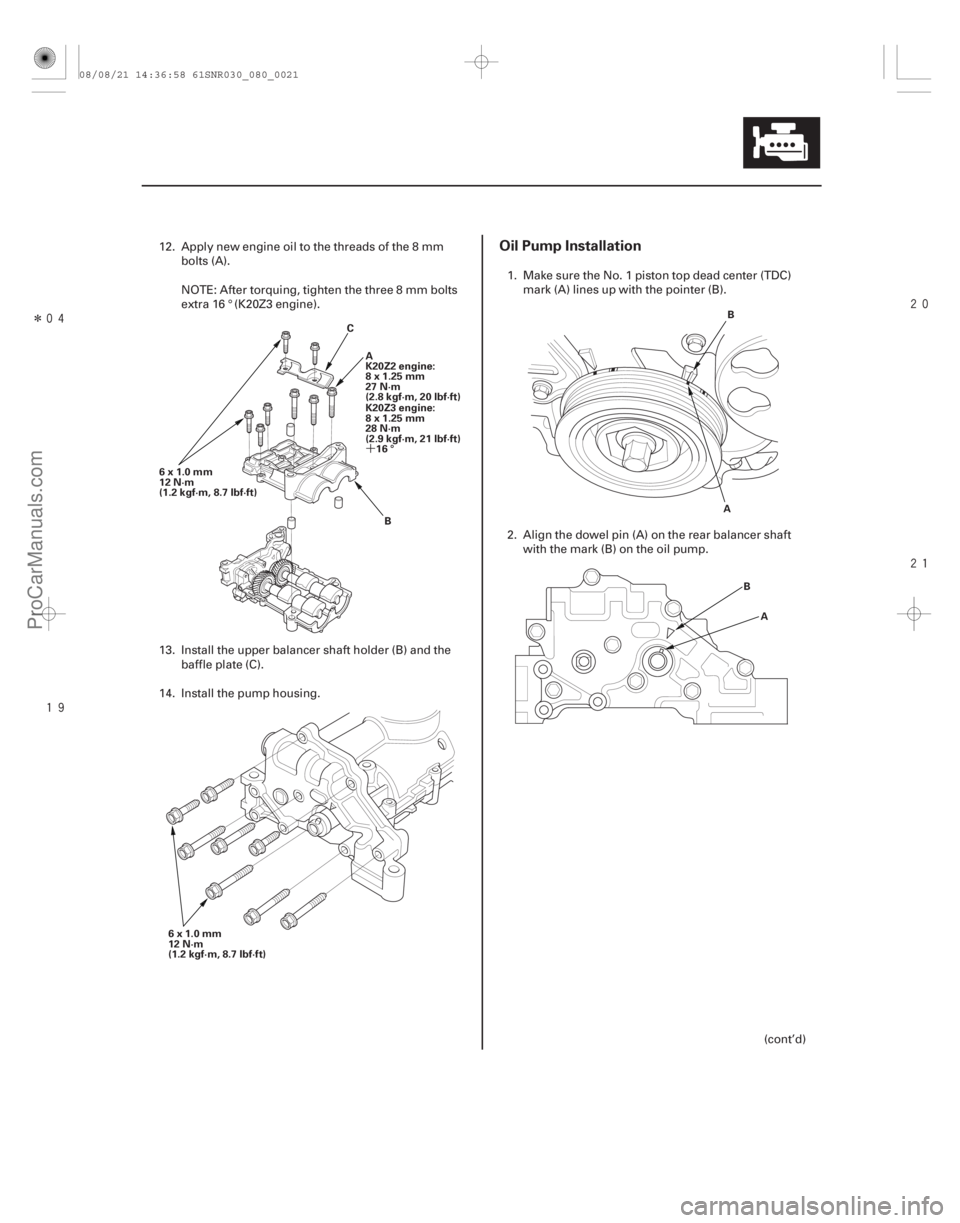
12. Apply new engine oil to the threads of the 8 mm bolts (A).
NOTE: After torquing, tighten the three 8 mm bolts
extra 16 ° (K20Z3 engine).
13. Install the upper balancer shaft holder (B) and the baffle plate (C).
14. Install the pump housing. 1. Make sure the No. 1 piston top dead center (TDC)
mark (A) lines up with the pointer (B).
2. Align the dowel pin (A) on the rear balancer shaft with the mark (B) on the oil pump.
(cont’d)
08/08/21 14:36:58 61SNR030_080_0021
ProCarManuals.com
DYNOMITE -2009-
Page 273 of 2893

A
8x1.25mm
22N·m(2.2kgf·m,16lbf·ft) 8x1.25mm
22 N·m
(2.2 kgf·m, 16 lbf·ft)A
10x1.25mm
44 N·m
(4.5 kgf·m, 33 lbf·ft)
10x1")
����
��������
����
8-22Engine Lubrication
Oil Pump Overhaul (cont’d)
A
8x1.25mm
22N·m(2.2kgf·m,16lbf·ft) 8x1.25mm
22 N·m
(2.2 kgf·m, 16 lbf·ft)A
10x1.25mm
44 N·m
(4.5 kgf·m, 33 lbf·ft)
10x1.25mm
44 N·m
(4.5 kgf·m, 33 lbf·ft) B
C
D B
A
6x1.0mm
12 N·m
(1.2 kgf·m, 8.7 lbf·ft)
3. To hold the rear balancer shaft, insert a 6 mm long pin punch (Snap-on PPC 108LA or equivalent) (A)
into the maintenance hole in the lower balancer
shaft holder and through the rear balancer shaft.
4. Apply new engine oil to the threads of the oil pump sprocket mounting bolt (A).
5. Loosely install the oil pump (B), then install the oil pump sprocket (C).
6. Tighten the oil pump mounting bolts and the oil pump sprocket mounting bolt.
7. Remove the 6 mm long pin punch (D). 8. Squeeze the new oil pump chain tensioner (A), then
install the set clip (B) on it as shown.
NOTE: The set clip is supplied with the oil pump
chain tensioner.
9. Install the new oil pump chain tensioner.
08/08/21 14:36:59 61SNR030_080_0022
ProCarManuals.com
DYNOMITE -2009-