����
�����
�(�#�'�����#���������
�����������������������)����
�´
�µ
�µ
�µ
�µ �µ
�µ
�µ
�µ
No picture is displayed
YES
NO
YES
NO YES
NO
YES
NO
23-338Navigation System
Symptom Troubleshooting
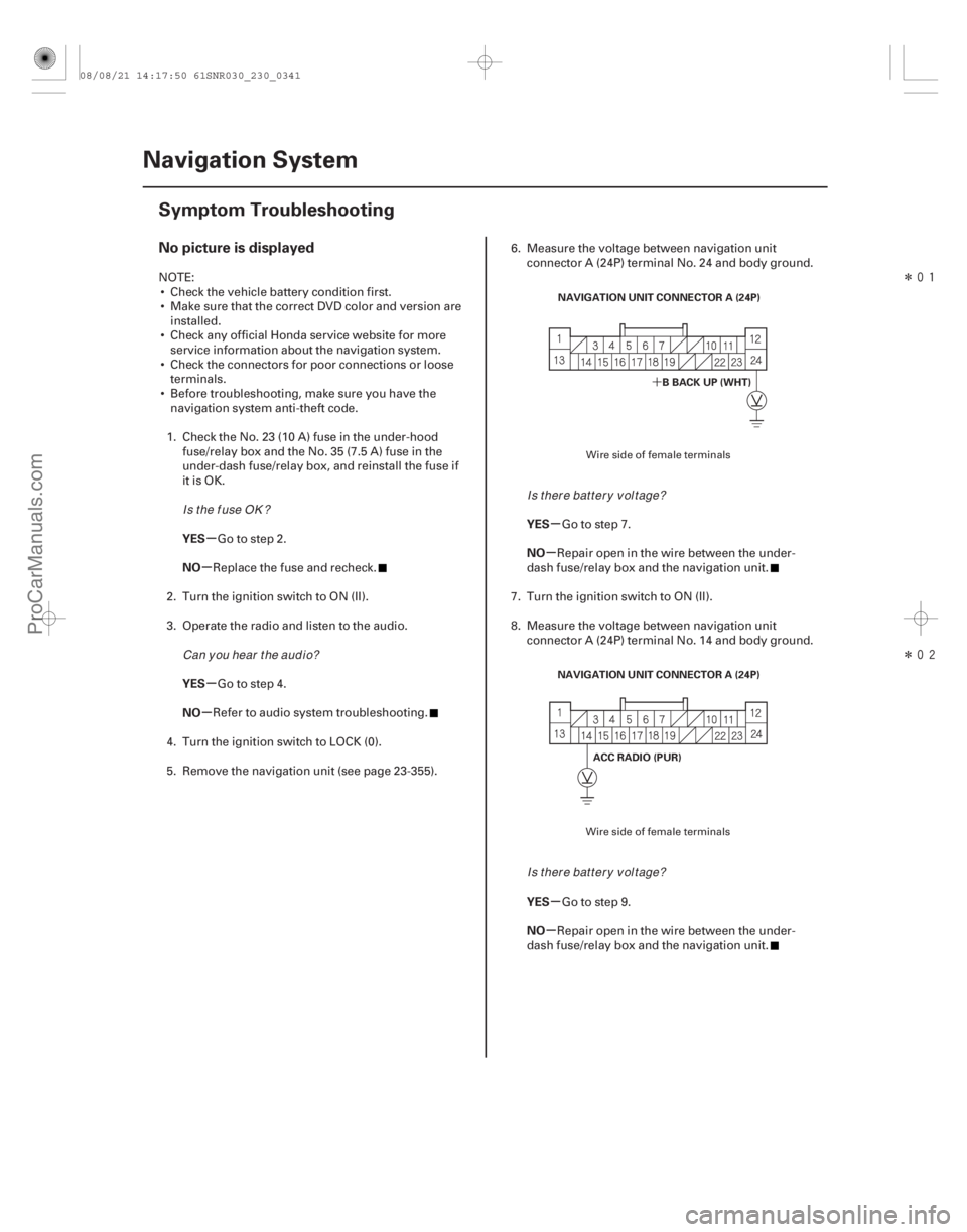
NAVIGATION UNIT CONNECTOR A (24P)
BBACKUP(WHT)
NAVIGATION UNIT CONNECTOR A (24P) ACC RADIO (PUR)
NOTE: Check the vehicle battery condition first.
Make sure that the correct DVD color and version are installed.
Check any official Honda service website for more service information about the navigation system.
Check the connectors for poor connections or loose terminals.
Before troubleshooting, make sure you have the navigation system anti-theft code.
1. Check the No. 23 (10 A) fuse in the under-hood fuse/relay box and the No. 35 (7.5 A) fuse in the
under-dash fuse/relay box, and reinstall the fuse if
it is OK.
Go to step 2.
Replace the fuse and recheck.
2. Turn the ignition switch to ON (II).
3. Operate the radio and listen to the audio.
Go to step 4.
Refer to audio system troubleshooting.
4. Turn the ignition switch to LOCK (0).
5. Remove the navigation unit (see page 23-355). 6. Measure the voltage between navigation unit
connector A (24P) terminal No. 24 and body ground.
Go to step 7.
Repair open in the wire between the under-
dash fuse/relay box and the navigation unit.
7. Turn the ignition switch to ON (II).
8. Measure the voltage between navigation unit connector A (24P) terminal No. 14 and body ground.
Go to step 9.
Repair open in the wire between the under-
dash fuse/relay box and the navigation unit.
Wire side of female terminals
Wire side of female terminals
IsthefuseOK? Can y ou hear t he aud i o? Is there battery voltage?
Is there battery voltage?
08/08/21 14:17:50 61SNR030_230_0341
ProCarManuals.com
DYNOMITE -2009-
����
�(�#�'�����#�����
�������������������
�������)����
Cavity Wire Test condition Test: Desired resultPossible cause if result is not obtained
Cavity Wire Test condition Test: Desired resultPossible cause if result is not obtained
23-388HandsFreeLink System
Control Unit Input Test/Replacement
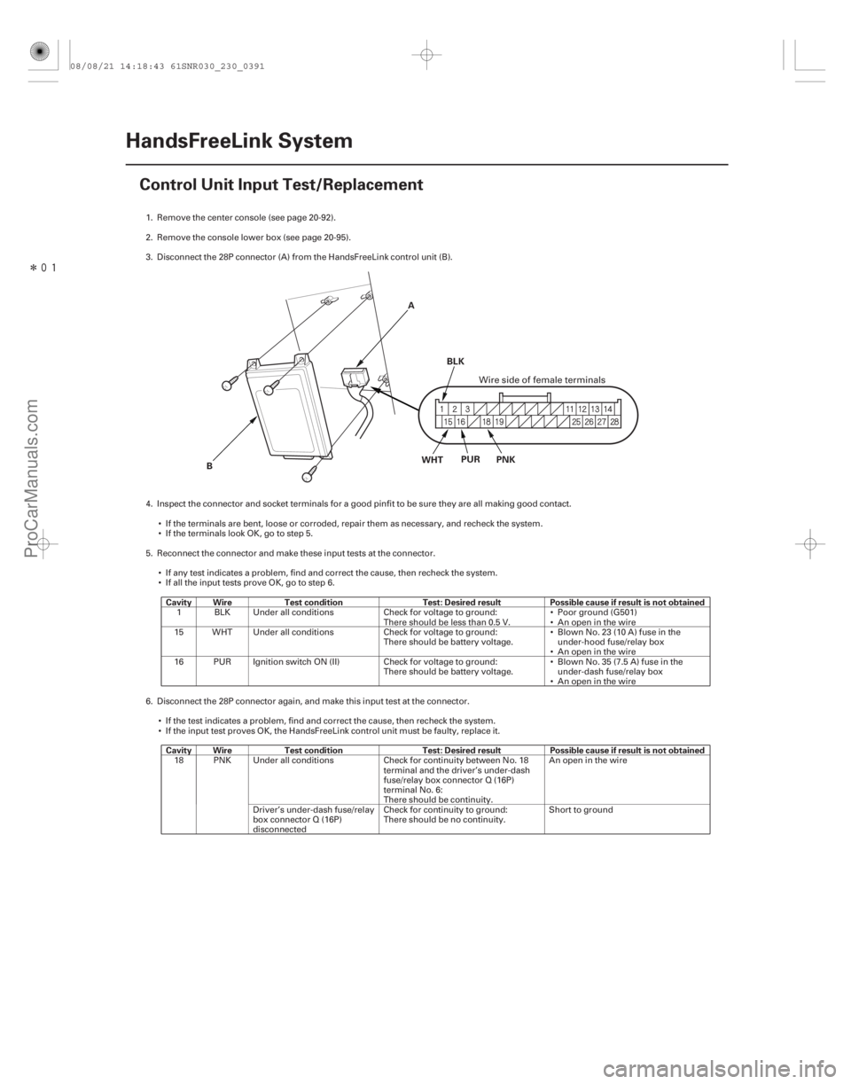
B
A
WHT PUR
PNK
BLK
1. Remove the center console (see page 20-92).
2. Remove the console lower box (see page 20-95).
3. Disconnect the 28P connector (A) from the HandsFreeLink control unit (B).
4. Inspect the connector and socket terminals for a good pinfit to be sure they are all making good contact.
If the terminals are bent, loose or corroded, repair them as necessary, and recheck the system.
IftheterminalslookOK,gotostep5.
5. Reconnect the connector and make these input tests at the connector. If any test indicates a problem, find and correct the cause, then recheck the system.
If all the input tests prove OK, go to step 6.
1 BLK Under all conditions Check for voltage to ground:
There should be less than 0.5 V.Poor ground (G501)
An open in the wire
15 WHT Under all conditions Check for voltage to ground: There should be battery voltage.Blown No. 23 (10 A) fuse in the
under-hood fuse/relay box
An open in the wire
16 PUR Ignition switch ON (II) Check for voltage to ground: There should be battery voltage.Blown No. 35 (7.5 A) fuse in the
under-dash fuse/relay box
An open in the wire
6. Disconnect the 28P connector again, and make this input test at the connector. If the test indicates a problem, find and correct the cause, then recheck the system.
If the input test proves OK, the HandsFreeLink control unit must be faulty, replace it.
18 PNK Under all conditions Check for continuity between No. 18 terminal and the driver’s under-dash
fuse/relay box connector Q (16P)
terminal No. 6:
There should be continuity.An open in the wire
Driver’s under-dash fuse/relay
box connector Q (16P)
disconnected Check for continuity to ground:
There should be no continuity.
Short to ground
Wire side of female terminals
08/08/21 14:18:43 61SNR030_230_0391
ProCarManuals.com
DYNOMITE -2009-