Page 102 of 2893
����
Special Tools Required
5-3
Engine Removal
C
A
B
B
AB
Engine hanger adapter VSB02C000015
Engine support hanger, A and Red")
�Ì�Ï
���
����
����
�(�#�'�����������
��������������������� �����)����
Special Tools Required
5-3
Engine Removal
C
A
B
B
AB
Engine hanger adapter VSB02C000015
Engine support hanger, A and Reds AAR-T 1256
2006 Civic engine hanger VSB02C000025
Front subframe adapter VSB02C000016
Universal lifting eyelet 07AAK-SNAA120 : These special tools are available through Honda
Canada Inc. Technical Tools Department; FAX 866-398-8665/e-mail: ch_technicaltools ch.honda.
com
NOTE: Use fender covers to avoid damaging painted surfaces.
To avoid damaging the wire and terminals, unplug the wiring connectors carefully while holding the
connector portion.
Mark all wiring and hoses to avoid misconnection. Also, be sure that they do not contact other wiring or
hoses, or interfere with other parts.
1. Secure the hood in the wide open position (support rod in the lower hole).
2. Relieve the fuel pressure (see page 11-322).
3. Do the battery removal procedure (see page 22-69).
4. Disconnect the vacuum hose and the breather pipe, then remove the intake air duct (see step 2 on page
9-3).
5. Remove the air cleaner assembly (see page 11-345).
6. Remove the under-cowl panel (see step 4 on page 20-164). 7. Disconnect the connector (A), and remove the
harness clamps (B), then remove the pipe (C).
8. Disconnect the battery cables (A) from the under- hood fuse/relay box.
9. Remove the harness clamp (B). (cont’d)
08/08/21 14:20:21 61SNR030_050_0003
ProCarManuals.com
DYNOMITE -2009-
Page 122 of 2893
 A
B A
B
C
6x1.0mm
10 N·m
(1.0 kgf·m, 7.2 lbf·ft)
C
56. Install the ECM/PCM (A), then install the ECM/PCM
cover (B).
57. Connec")
��
������ ��
�
5-23
B
A
6x1.0mm
10 N·m
(1.0 kgf·m, 7.2 lbf·ft) A
B A
B
C
6x1.0mm
10 N·m
(1.0 kgf·m, 7.2 lbf·ft)
C
56. Install the ECM/PCM (A), then install the ECM/PCM
cover (B).
57. Connect the battery cables (A) to the under-hood fuse/relay box.
58. Install the harness clamp (B). 59. Install the pipe (A).
60. Connect the connector (B), and install the harness
clamps (C).
61. Install the under cowl-panel (see step 4 on page 20-164).
62. Install the air cleaner assembly (see page 11-345).
63. Install the front wheels.
64. Do the battery installation procedure (see page 22-69).
65. Inspect for fuel leaks. Turn the ignition switch to ON (II) (do not operate the starter) so the fuel pump
runs for about 2 seconds and pressurizes the fuel
line. Repeat this operation three times, then check
for fuel leakage at any point in the fuel line.
66. Refill the engine with engine oil (see step 4 on page 8-10).
(cont’d)
08/08/21 14:21:01 61SNR030_050_0023
ProCarManuals.com
DYNOMITE -2009-
Page 125 of 2893
����
����
�����
5-25
A
B
A B
10x1.25mm
49 N·m
(5.0 kgf·m, 36 lbf·ft)
6x1.0mm
10 N·m
(1.0 kgf·m, 7.2 lbf·ft)
12x1.25mm
64 N·m
(6.5 kgf·m, 47 lbf·ft) D
A C
B
6x1.0mm
10 N·m
(1.0 kgf·m, 7.2 lbf·ft)
3. Remove the ground cable (A), then remove the side
engine mount bracket (B).
4. Remove the side engine mount stiffener (A), then remove the side engine mount (B).
5. Install the side engine mount, then install the side engine mount stiffener. 6. Install the side engine mount bracket (A), loosely
tighten the new bolt and nut (B), then loosely
tighten the bolt (C).
7. Install the ground cable (D).
8. Remove the air cleaner assembly (see page 11-345).
(cont’d)
Replace. Replace.
08/08/21 14:21:02 61SNR030_050_0025
ProCarManuals.com
DYNOMITE -2009-
Page 128 of 2893
�
���
��
�
��
M/T model
A/T model
5-28Engine Assembly
Side Engine Mount Replacement (cont’d)
14x1.5mm
93 N·m
(9.5 kgf·m, 69 lbf·ft)
12x1.25mm
64 N·m
(6.5 kgf·m, 47 lbf·ft)
12x1.25mm
64 N·m
(6.5 kgf·m, 47 lbf·ft)
12x1.25mm
64 N·m
(6.5 kgf·m, 47 lbf·ft)
12x1.25mm
64 N·m
(6.5 kgf·m, 47 lbf·ft)
17. Raise the vehicle on the lift.
18. Tighten the lower torque rod mounting bolt.
19. Lower the vehicle on the lift.
20. Install the air cleaner assembly (see page 11-345). 21. Install the upper torque rod, then tighten the new
upper torque rod mounting bolts in the numbered
sequence shown.
Replace.
Replace.
Replace.
Replace.
08/08/21 14:21:04 61SNR030_050_0028
ProCarManuals.com
DYNOMITE -2009-
Page 129 of 2893
�
�����
�(�#�'�����������
��������������������� �����)���
5-295-29
Transmission Mount Replacement
12x1.25mm
64 N·m
(6.5 kgf·m, 47 lbf·ft) A
22. Raise the vehicle on the lift.
23. M/T model: Tighten the front mount mounting bolt.
24. Install the splash shield (see step 40 on page 5-20).1. Loosen the upper torque rod mounting bolt (A).
2. Remove the air cleaner assembly (see page 11-345).
3. Remove the engine control module (ECM)/
powertrain control module (PCM) cover, then
remove the three bolts securing the ECM/PCM (see
step 10 on page 5-4).
4. Remove the under hood fuse/relay box from the ECM/PCM bracket, then remove the ECM/PCM
bracket(seestep13onpage5-4).
(cont’d)
08/08/21 14:21:04 61SNR030_050_0029
ProCarManuals.com
DYNOMITE -2009-
Page 130 of 2893
�
�����
�(�#�'�����������
��������������������� �����)���
5-295-29
Transmission Mount Replacement
12x1.25mm
64 N·m
(6.5 kgf·m, 47 lbf·ft) A
22. Raise the vehicle on the lift.
23. M/T model: Tighten the front mount mounting bolt.
24. Install the splash shield (see step 40 on page 5-20).1. Loosen the upper torque rod mounting bolt (A).
2. Remove the air cleaner assembly (see page 11-345).
3. Remove the engine control module (ECM)/
powertrain control module (PCM) cover, then
remove the three bolts securing the ECM/PCM (see
step 10 on page 5-4).
4. Remove the under hood fuse/relay box from the ECM/PCM bracket, then remove the ECM/PCM
bracket(seestep13onpage5-4).
(cont’d)
08/08/21 14:21:04 61SNR030_050_0029
ProCarManuals.com
DYNOMITE -2009-
Page 133 of 2893
�
�����
����
�(�#�'�����������
��������������������� �����)����
5-325-32 Engine Assembly
Transmission Mount Replacement
(cont’d)
Lower Torque Rod Replacement
12x1.25mm
64 N·m
(6.5 kgf·m, 47 lbf·ft) A
A
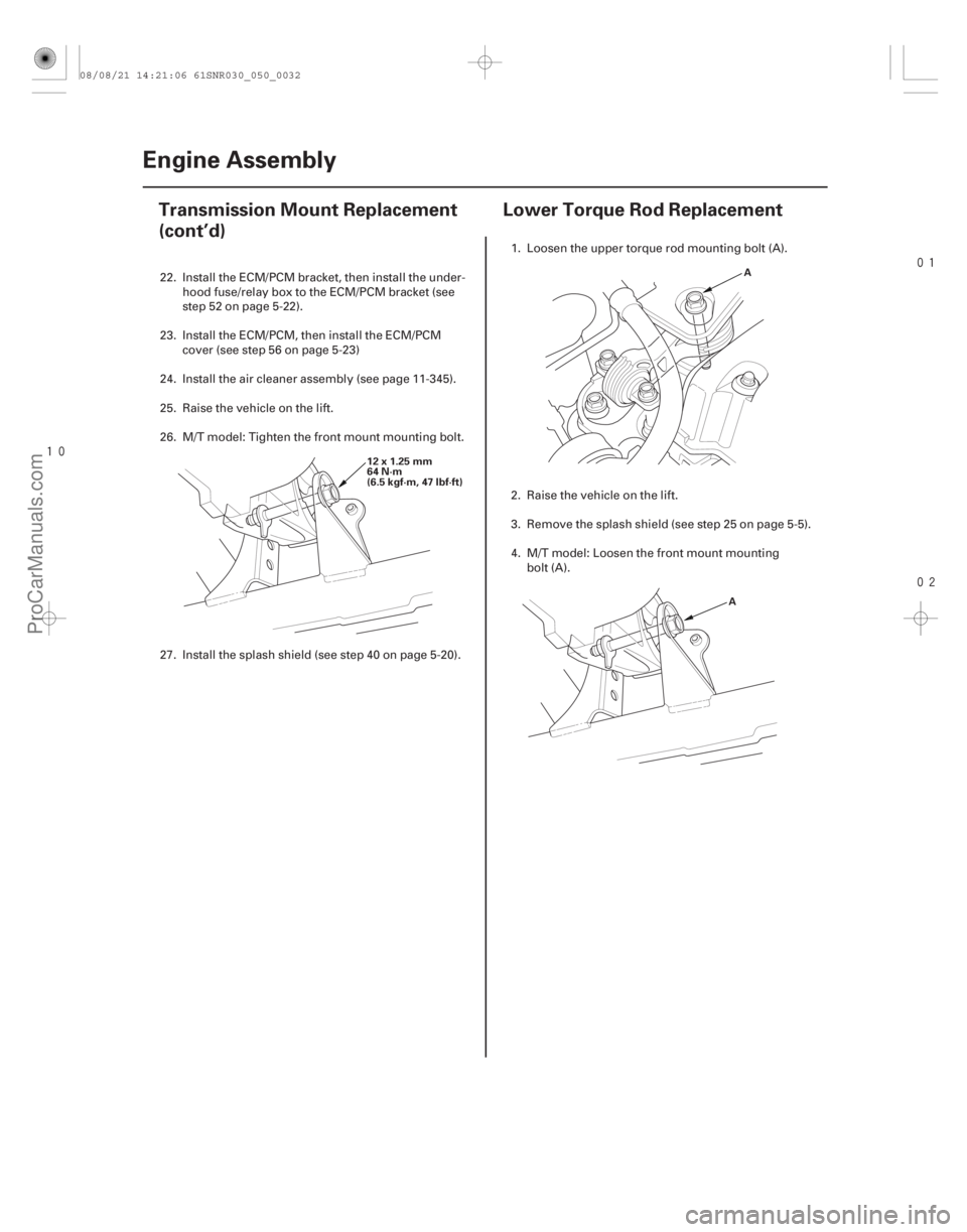
22. Install the ECM/PCM bracket, then install the under- hood fuse/relay box to the ECM/PCM bracket (see
step 52 on page 5-22).
23. Install the ECM/PCM, then install the ECM/PCM cover (see step 56 on page 5-23)
24. Install the air cleaner assembly (see page 11-345).
25. Raise the vehicle on the lift.
26. M/T model: Tighten the front mount mounting bolt.
27. Install the splash shield (see step 40 on page 5-20). 1. Loosen the upper torque rod mounting bolt (A).
2. Raise the vehicle on the lift.
3. Remove the splash shield (see step 25 on page 5-5).
4. M/T model: Loosen the front mount mounting
bolt (A).
08/08/21 14:21:06 61SNR030_050_0032
ProCarManuals.com
DYNOMITE -2009-
Page 134 of 2893
�
�����
����
�(�#�'�����������
��������������������� �����)����
5-325-32 Engine Assembly
Transmission Mount Replacement
(cont’d)
Lower Torque Rod Replacement
12x1.25mm
64 N·m
(6.5 kgf·m, 47 lbf·ft) A
A
22. Install the ECM/PCM bracket, then install the under- hood fuse/relay box to the ECM/PCM bracket (see
step 52 on page 5-22).
23. Install the ECM/PCM, then install the ECM/PCM cover (see step 56 on page 5-23)
24. Install the air cleaner assembly (see page 11-345).
25. Raise the vehicle on the lift.
26. M/T model: Tighten the front mount mounting bolt.
27. Install the splash shield (see step 40 on page 5-20). 1. Loosen the upper torque rod mounting bolt (A).
2. Raise the vehicle on the lift.
3. Remove the splash shield (see step 25 on page 5-5).
4. M/T model: Loosen the front mount mounting
bolt (A).
08/08/21 14:21:06 61SNR030_050_0032
ProCarManuals.com
DYNOMITE -2009-