Page 458 of 2893
����
�µ
�µ
�µ
�µ �µ
�µ
�µ
�µ
�µ
�µ
�µ
�µ
YES
NO
YES
NO
YES
NO
YES
NO
YES
NO
YES
NO
DTC P050A:
11-13511-135
8. Check for damage on the CMP sens")
�(�#�'��������� �����
�����������������������)����
�µ
�µ
�µ
�µ �µ
�µ
�µ
�µ
�µ
�µ
�µ
�µ
YES
NO
YES
NO
YES
NO
YES
NO
YES
NO
YES
NO
DTC P050A:
11-13511-135
8. Check for damage on the CMP sensor B pulser
plate (see page 6-41).
Replace the CMP sensor B pulser plate
(see page 6-41), then go to step 11.
Go to step 9.
9. Turn the ignition switch to LOCK (0).
10. Replace CMP sensor B (see page 11-222).
11. Turn the ignition switch to ON (II).
12. Reset the ECM/PCM with the HDS.
13. Do the ECM/PCM idle learn procedure (see page 11-310).
14. Start the engine, and let it idle for 10 seconds.
15. Check for Temporary DTCs or DTCs with the HDS.
Check for poor connections or loose
terminals at CMP sensor B and the ECM/PCM, then
go to step 1.
Troubleshooting is complete. If any other
Temporary DTCs or DTCs are indicated, go to the
indicated DTC’s troubleshooting. NOTE: Before you troubleshoot, record all freeze data
and any on-board snapshot, and review the general
troubleshooting information (see page 11-3).
1. Turn the ignition switch to ON (II).
2. Check for Temporary DTCs or DTCs with the HDS.
Go to the indicated DTC’s troubleshooting.
Go to step 3.
3. Check for poor connections or a blockage at the intake air duct.
Go to step 4.
Reconnect or repair the intake air duct, then
go to step 20.
4. Check for damage to the air cleaner housing.
Go to step 5.
Replace the air cleaner housing (see page
11-345), then go to step 20.
5. Check for dirt or debris in the air cleaner element.
Replace the air cleaner element or remove
debris (see page 11-346), then go to step 20.
Go to step 6.
(cont’d)Cold Start Idle Air Control
System Performance Problem
Is the pulser plate damaged?
I s DT C P0369 i nd i cat ed ? Ar e any T empor ar y DT Cs or DT Cs ot her t han
P05 0A i nd i cat ed ?
Is it OK ?Is it OK ?Is it dirty?
08/08/21 14:18:56 61SNR030_110_0135
ProCarManuals.com
DYNOMITE -2009-
Page 460 of 2893
����
�µ
�µ
�µ
�µ �µ
�µ
�µ
�µ
�µ
�µ
�µ
�µ
YES
NO
YES
NO
YES
NO
YES
NO
YES
NO
YES
NO
DTC P050B:
11-13711-137
20. Turn the ignition switch to ON")
�(�#�'��������� �����
�����������������������)����
�µ
�µ
�µ
�µ �µ
�µ
�µ
�µ
�µ
�µ
�µ
�µ
YES
NO
YES
NO
YES
NO
YES
NO
YES
NO
YES
NO
DTC P050B:
11-13711-137
20. Turn the ignition switch to ON (II).
21. Reset the ECM/PCM with the HDS.
22. Do the ECM/PCM idle learn procedure (see page
11-310).
23. Let the engine cool until the value of ECT SENSOR 1 is 50 °C (122 °F) or less.
24. Start the engine, and let it idle for 10 seconds or more.
25. Check for Temporary DTCs or DTCs with the HDS.
Check for poor connections or loose
terminals at the throttle body, the MAF sensor/IAT
sensor, and the ECM/PCM, then go to step 1.
Go to step 26.
26. Monitor the OBD STATUS for DTC P050A in the DTCs MENU with the HDS.
Troubleshooting is complete. If any other
Temporary DTCs or DTCs were indicated in step 25,
go to the indicated DTC’s troubleshooting.
If the screen indicates FAILED, check for poor
connections or loose terminals at the throttle body,
the MAF sensor/IAT sensor, and the ECM/PCM,
then go to step 1. If the screen indicates
EXECUTING, keep idling until a result comes on. If
the screen indicates OUT OF CONDITION, go to
step 23. NOTE: Before you troubleshoot, record all freeze data
and any on-board snapshot, and review the general
troubleshooting information (see page 11-3).
1. Turn the ignition switch to ON (II).
2. Check for Temporary DTCs or DTCs with the HDS.
Go to the indicated DTC’s troubleshooting.
Go to step 3.
3. Check for poor connections or a blockage at the intake air duct.
Go to step 4.
Reconnect or repair the intake air duct, then
go to step 25.
4. Check for damage to the air cleaner housing.
Go to step 5.
Replace the air cleaner housing (see page
11-345), then go to step 25.
5. Check for dirt or debris in the air cleaner element.
Replace the air cleaner element or remove
debris (see page 11-346), then go to step 25.
Go to step 6.
(cont’d)Cold Start Ignition Timing
Control System Performance Problem
Is DT C P050A ind icated ?
Does t he scr een i nd i cat e PASSE D? Ar e any T empor ar y DT Cs or DT Cs ot her t han
P05 0B i nd i cat ed ?
Is it OK ?Is it OK ?Is it dirty?
08/08/21 14:18:56 61SNR030_110_0137
ProCarManuals.com
DYNOMITE -2009-
Page 545 of 2893
���
�(�#�'�����������������������
�������
� �����)���� ���
�(�#�'�����������������������
��������� �����)���
11-22211-222 PGM-FI System
CMP Sensor B Replacement
CKP Sensor Replacement
C
B
A 12 N·m
(1.2 kgf·m,
8.7 lbf·ft)
12 N·m
(1.2 kgf·m, 8.7 lbf·ft)
A B
C
1. Remove the air cleaner (see page 11-345).
2. K20Z2 engine: Remove the EGR valve (see page
11-370).
3. Disconnect the CMP sensor B 3P connector (A).
4. Remove CMP sensor B.
5. Install the parts in the reverse order of removal with a new O-ring (C). 1. Disconnect the CKP sensor 3P connector (A).
2. Remove the CKP sensor (B).
3. Install the parts in the reverse order of removal
with a new O-ring (C).
4. Do the CKP pattern clear/CKP pattern learn procedure with the HDS (see page 11-4).
08/08/21 14:23:36 61SNR030_110_0222
ProCarManuals.com
DYNOMITE -2009-
Page 548 of 2893
���
����
�(�#������������������������������
�
� �����)����
11-22511-225
ECT Sensor 1 Replacement ECT Sensor 2 Replacement
A B
C
B
12 N·m (1.2")
���
�����(�#�'�����������������������������
�
� �����)���
����
�(�#�'�����������������������������
�
� �����)����
11-22511-225
ECT Sensor 1 Replacement ECT Sensor 2 Replacement
A B
C
B
12 N·m (1.2 kgf·m, 8.7 lbf·ft) C
A
B
12 N·m
(1.2 kgf·m, 8.7 lbf·ft)A
C
1. Drain the engine coolant (see page 10-8).
2. Remove the air cleaner (see page 11-345).
3. K20Z2 engine: Remove the EGR valve (see page 11-370).
4. Disconnect CMP sensor A 3P connector (A), and CMP sensor B 3P connector.
5. Remove the harness cover (C).
6. Disconnect the ECT sensor 1 2P connector (A).
7. Remove ECT sensor 1 (B).
8. Install the parts in the reverse order of removal with a new O-ring (C), then refill the radiator with
engine coolant (see page 10-8). 1. Drain the engine coolant (see page 10-8).
2. Remove the splash shield.
3. Disconnect the ECT sensor 2 2P connector (A), then
remove ECT sensor 2 (B).
4. Install the parts in the reverse order of removal with a new O-ring (C).
5. Install the splash shield.
6. Refill the radiator with engine coolant (see page 10-8).
08/08/21 14:23:38 61SNR030_110_0225
ProCarManuals.com
DYNOMITE -2009-
Page 619 of 2893
�������
�(�#�'�����������
�����������
�������
� �����)�
��
11-29511-295
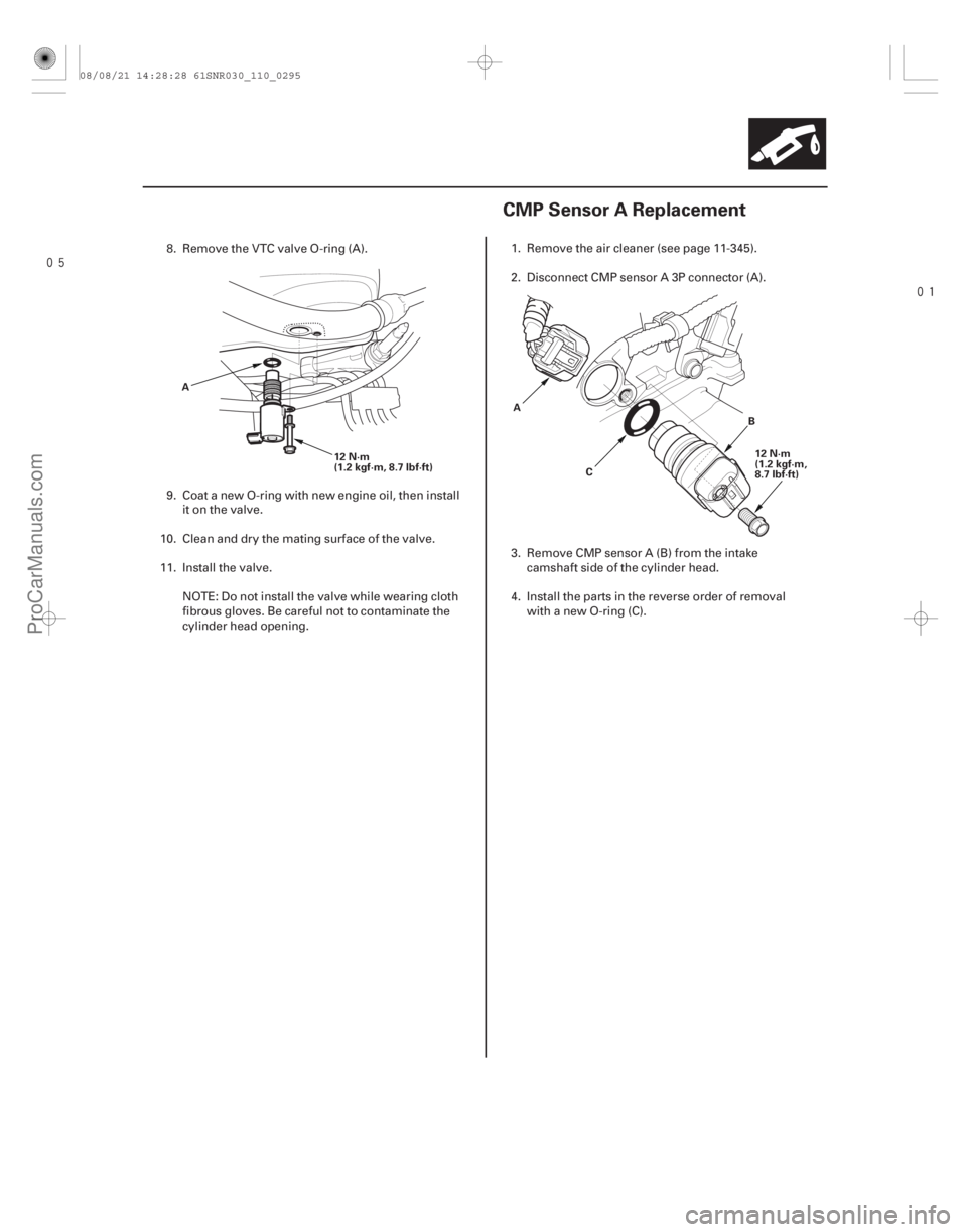
CMP Sensor A Replacement
12 N·m
(1.2 kgf·m, 8.7 lbf·ft)
A
12 N·m
(1.2 kgf·m,
8.7 lbf·ft)
B
C
A
8. Remove the VTC valve O-ring (A).
9. Coat a new O-ring with new engine oil, then install
it on the valve.
10. Clean and dry the mating surface of the valve.
11. Install the valve. NOTE: Do not install the valve while wearing cloth
fibrous gloves. Be careful not to contaminate the
cylinder head opening. 1. Remove the air cleaner (see page 11-345).
2. Disconnect CMP sensor A 3P connector (A).
3. Remove CMP sensor A (B) from the intake
camshaft side of the cylinder head.
4. Install the parts in the reverse order of removal with a new O-ring (C).
08/08/21 14:28:28 61SNR030_110_0295
ProCarManuals.com
DYNOMITE -2009-
Page 620 of 2893
�������
�(�#�'�����������
�����������
�������
� �����)�
��
11-29511-295
CMP Sensor A Replacement
12 N·m
(1.2 kgf·m, 8.7 lbf·ft)
A
12 N·m
(1.2 kgf·m,
8.7 lbf·ft)
B
C
A
8. Remove the VTC valve O-ring (A).
9. Coat a new O-ring with new engine oil, then install
it on the valve.
10. Clean and dry the mating surface of the valve.
11. Install the valve. NOTE: Do not install the valve while wearing cloth
fibrous gloves. Be careful not to contaminate the
cylinder head opening. 1. Remove the air cleaner (see page 11-345).
2. Disconnect CMP sensor A 3P connector (A).
3. Remove CMP sensor A (B) from the intake
camshaft side of the cylinder head.
4. Install the parts in the reverse order of removal with a new O-ring (C).
08/08/21 14:28:28 61SNR030_110_0295
ProCarManuals.com
DYNOMITE -2009-
Page 671 of 2893
���� K20Z2 engine:
K20Z3 engine:
11-342Intake Air System
Component Location Index
THROTTLE BODY
AIR CLEANER
INTAKE AIR RESONATOR
INTAKE AIR")
����
������(�#�'���������������������������������������)���� K20Z2 engine:
K20Z3 engine:
11-342Intake Air System
Component Location Index
THROTTLE BODY
AIR CLEANER
INTAKE AIR RESONATOR
INTAKE AIR BYPASS CONTROL
THERMAL VALVE ENGINE CONTROL MODULE (ECM)/
POWERTRAIN CONTROL MODULE (PCM)
THROTTLE BODY AIR CLEANER
INTAKE AIR RESONATOR
INTAKE AIR BYPASS CONTROL
THERMAL VALVE ENGINE CONTROL MODULE (ECM)
Test, page 11-343
Cleaning, page 11-344
Removal/Installation, page 11-348
Disassembly/Reassembly, page 11-350 Removal/Installation, page 11-345
Element Inspection/Replacement,
page 11-346
Removal/Installation,page 11-346
Test, page 11-344
Replacement, page 11-351 Update, page 11-227
Substitution, page 11-7
Replacement, page 11-228
08/08/21 14:31:07 61SNR030_110_0342
ProCarManuals.com
DYNOMITE -2009-
Page 674 of 2893
���
�(�#�'�����������������������
�������
� �����)���
11-34511-345
Air Cleaner Removal/Installation
C B
12 N·m
(1.2 kgf·m,
8.7 lbf·ft)
A
6. Raise and lower the engine speed, and make sure the vacuum gauge reading does not change as the
rpm changes.
If the vacuum reading changes, check for these
problems:
Misrouted, leaking, broken, or clogged intake air bypass control system vacuum lines.
A cracked or damaged intake air bypass control thermal valve. Replace the valve if needed
(see page 11-351). 1. Disconnect the MAF sensor/IAT sensor 5P
connector (A).
2. Remove the bolts (B).
3. Remove the air cleaner (C).
4. Install the parts in the reverse order of removal.
* : This illustration shows K20Z2 engine.
08/08/21 14:31:08 61SNR030_110_0345
ProCarManuals.com
DYNOMITE -2009-