Page 65 of 104

PERIODIC MAINTENANCE AND MINOR REPAIR
6-17
6
EAU21401
Valve clearance The valve clearance changes with use,
resulting in improper air-fuel mixture
and/or engine noise. To prevent this
from occurring, the valve clearance
must be adjusted by a Yamaha dealer
at the intervals specified in the periodic
maintenance and lubrication chart.
EAU21771
Tires To maximize the performance, durabil-
ity, and safe operation of your motor-
cycle, note the following points
regarding the specified tires.
Tire air pressure
The tire air pressure should be checked
and, if necessary, adjusted before each
ride.
WARNING
EWA10500
�
The tire air pressure must be
checked and adjusted on cold
tires (i.e., when the temperature
of the tires equals the ambient
temperature).
�
The tire air pressure must be ad-
justed in accordance with the
riding speed and with the total
weight of rider, passenger, car-
go, and accessories approvedfor this model.
WARNING
EWA11020
Because loading has an enormous
impact on the handling, braking,
performance and safety characteris-
tics of your motorcycle, you should
keep the following precautions in
mind.
Tire air pressure (measured on cold
tires):
0–90 kg (0–198 lb):
Fr o nt :
250 kPa (36 psi) (2.50 kgf/cm²)
Rear:
290 kPa (42 psi) (2.90 kgf/cm²)
90–202 kg (198–445 lb):
Fr o nt :
250 kPa (36 psi) (2.50 kgf/cm²)
Rear:
290 kPa (42 psi) (2.90 kgf/cm²)
High-speed riding:
Fr o nt :
250 kPa (36 psi) (2.50 kgf/cm²)
Rear:
290 kPa (42 psi) (2.90 kgf/cm²)
Maximum load*:
202 kg (445 lb)
* Total weight of rider, passenger, car-
go and accessories
U5VYE1E0.book Page 17 Tuesday, September 7, 2004 9:09 AM
Page 66 of 104

PERIODIC MAINTENANCE AND MINOR REPAIR
6-18
6
�
NEVER OVERLOAD THE
MOTORCYCLE! Operation of an
overloaded motorcycle may re-
sult in tire damage, loss of con-
trol, or severe injury. Make sure
that the total weight of rider,
passenger, cargo, and accesso-
ries does not exceed the speci-
fied maximum load for the
vehicle.
�
Do not carry along loosely
packed items, which can shift
during a ride.
�
Securely pack the heaviest
items close to the center of the
motorcycle and distribute the
weight evenly on both sides.
�
Adjust the suspension and tire
air pressure with regard to the
load.
�
Check the tire condition and airpressure before each ride.Tire inspection
The tires must be checked before each
ride. If the center tread depth reaches
the specified limit, if the tire has a nail or
glass fragments in it, or if the sidewall is
cracked, have a Yamaha dealer re-
place the tire immediately.
NOTE:The tire tread depth limits may differ
from country to country. Always complywith the local regulations.
WARNING
EWA10470
�
Have a Yamaha dealer replace
excessively worn tires. Besides
being illegal, operating the vehi-
cle with excessively worn tires
decreases riding stability and
can lead to loss of control.
�
The replacement of all wheel
and brake related parts, includ-
ing the tires, should be left to a
Yamaha dealer, who has the
necessary professional knowl-edge and experience.
Tire information
1. Tire sidewall
2. Tire tread depthMinimum tire tread depth (front and
rear):
1.6 mm (0.06 in)
1. Tire air valve
2. Tire air valve core
3. Tire air valve cap with seal
U5VYE1E0.book Page 18 Tuesday, September 7, 2004 9:09 AM
Page 67 of 104

PERIODIC MAINTENANCE AND MINOR REPAIR
6-19
6 This motorcycle is equipped with cast
wheels and tubeless tires with valves.
WARNING
EWA10480
�
The front and rear tires should
be of the same make and de-
sign, otherwise the handling
characteristics of the motor-
cycle cannot be guaranteed.
�
After extensive tests, only the
tires listed below have been ap-
proved for this model by
Yamaha Motor Co., Ltd.
�
Always make sure that the valve
caps are securely installed to
prevent air pressure leakage.
�
Use only the tire valves and
valve cores listed below to
avoid tire deflation during ahigh-speed ride.
WARNING
EWA10600
This motorcycle is fitted with super-
high-speed tires. Note the following
points in order to make the most ef-
ficient use of these tires.�
Use only the specified replace-
ment tires. Other tires may run
the danger of bursting at super
high speeds.
�
Brand-new tires can have a rela-
tively poor grip on certain road
surfaces until they have been“broken in”. Therefore, it is ad-
visable before doing any high-
speed riding to ride conserva-
tively for approximately 100 km
(60 mi) after installing a new tire.
�
The tires must be warmed up
before a high-speed run.
�
Always adjust the tire air pres-
sure according to the operatingconditions.
Front tire:
Size:
120/70 ZR17M/C (58W)
Manufacturer/model:
MICHELIN/Pilot POWER C
DUNLOP/D218FL
Rear tire:
Size:
190/50 ZR17M/C (73W)
Manufacturer/model:
MICHELIN/Pilot POWER G
DUNLOP/D218L
FRONT and REAR:
Tire air valve:
TR412
Va l ve c o r e :
#9000A (original)
U5VYE1E0.book Page 19 Tuesday, September 7, 2004 9:09 AM
Page 68 of 104

PERIODIC MAINTENANCE AND MINOR REPAIR
6-20
6
EAU21960
Cast wheels To maximize the performance, durabil-
ity, and safe operation of your vehicle,
note the following points regarding the
specified wheels.�
The wheel rims should be checked
for cracks, bends or warpage be-
fore each ride. If any damage is
found, have a Yamaha dealer re-
place the wheel. Do not attempt
even the smallest repair to the
wheel. A deformed or cracked
wheel must be replaced.
�
The wheel should be balanced
whenever either the tire or wheel
has been changed or replaced. An
unbalanced wheel can result in
poor performance, adverse han-
dling characteristics, and a short-
ened tire life.
�
Ride at moderate speeds after
changing a tire since the tire sur-
face must first be “broken in” for it
to develop its optimal characteris-
tics.
EAU33890
Adjusting the clutch lever free
play The clutch lever free play should mea-
sure 10.0–15.0 mm (0.39–0.59 in) as
shown. Periodically check the clutch le-
ver free play and, if necessary, adjust it
as follows.
To increase the clutch lever free play,
turn the adjusting bolt at the clutch lever
in direction (a). To decrease the clutch
lever free play, turn the adjusting bolt in
direction (b).
NOTE:If the specified clutch lever free play
cannot be obtained as describedabove, proceed as follows.
1. Fully turn the adjusting bolt at the
clutch lever in direction (a) to loos-
en the clutch cable.
2. Loosen the locknut at the crank-
case.
3. To increase the clutch lever free
play, turn the adjusting nut in direc-
tion (a). To decrease the clutch le-
ver free play, turn the adjusting nut
in direction (b).
4. Tighten the locknut.
1. Clutch lever free play adjusting bolt
2. Clutch lever free play
1. Locknut
2. Clutch lever free play adjusting nut (crank-
case)
U5VYE1E0.book Page 20 Tuesday, September 7, 2004 9:09 AM
Page 69 of 104

PERIODIC MAINTENANCE AND MINOR REPAIR
6-21
6
EAU22270
Adjusting the rear brake light
switch The rear brake light switch, which is ac-
tivated by the brake pedal, is properly
adjusted when the brake light comes
on just before braking takes effect. If
necessary, adjust the brake light switch
as follows.
Turn the adjusting nut while holding the
rear brake light switch in place. To
make the brake light come on earlier,
turn the adjusting nut in direction (a). To
make the brake light come on later, turn
the adjusting nut in direction (b).
EAU22390
Checking the front and rear
brake pads The front and rear brake pads must be
checked for wear at the intervals spec-
ified in the periodic maintenance and
lubrication chart.
EAU22410
Front brake pads
Each front brake pad is provided with a
wear indicator, which allows you to
check the brake pad wear without hav-
ing to disassemble the brake. To check
the brake pad wear, check the position
of the wear indicator while applying the
brake. If a brake pad has worn to thepoint that the wear indicator almost
touches the brake disc, have a Yamaha
dealer replace the brake pads as a set.
EAU22500
Rear brake pads
Check each rear brake pad for damage
and measure the lining thickness. If a
brake pad is damaged or if the lining
thickness is less than 1.0 mm (0.04 in),
have a Yamaha dealer replace the
brake pads as a set.
1. Rear brake light switch
2. Rear brake light switch adjusting nut
1. Brake pad wear indicator
1. Lining thickness
U5VYE1E0.book Page 21 Tuesday, September 7, 2004 9:09 AM
Page 70 of 104

PERIODIC MAINTENANCE AND MINOR REPAIR
6-22
6
EAU22580
Checking the brake fluid level Front brake
Rear brake
Insufficient brake fluid may allow air to
enter the brake system, possibly caus-
ing it to become ineffective.Before riding, check that the brake fluid
is above the minimum level mark and
replenish if necessary. A low brake fluid
level may indicate worn brake pads
and/or brake system leakage. If the
brake fluid level is low, be sure to check
the brake pads for wear and the brake
system for leakage.
Observe these precautions:
�
When checking the fluid level,
make sure that the top of the brake
fluid reservoir is level.
�
Use only the recommended quality
brake fluid, otherwise the rubber
seals may deteriorate, causing
leakage and poor braking perfor-
mance.
�
Refill with the same type of brake
fluid. Mixing fluids may result in a
harmful chemical reaction and
lead to poor braking performance.
�
Be careful that water does not en-
ter the brake fluid reservoir when
refilling. Water will significantly
lower the boiling point of the fluid
and may result in vapor lock.
�
Brake fluid may deteriorate paint-
ed surfaces or plastic parts. Al-
ways clean up spilled fluid
immediately.
�
As the brake pads wear, it is nor-
mal for the brake fluid level to grad-
ually go down. However, if the
brake fluid level goes down sud-
denly, have a Yamaha dealer
check the cause.
1. Minimum level mark
1. Minimum level mark
Recommended brake fluid:
DOT 4
U5VYE1E0.book Page 22 Tuesday, September 7, 2004 9:09 AM
Page 71 of 104

PERIODIC MAINTENANCE AND MINOR REPAIR
6-23
6
EAU22730
Changing the brake fluid Have a Yamaha dealer change the
brake fluid at the intervals specified in
the NOTE after the periodic mainte-
nance and lubrication chart. In addition,
have the oil seals of the master cylin-
ders and calipers as well as the brake
hoses replaced at the intervals listed
below or whenever they are damaged
or leaking.�
Oil seals: Replace every two
years.
�
Brake hoses: Replace every four
years.
EAU22760
Drive chain slack The drive chain slack should be
checked before each ride and adjusted
if necessary.
EAU22770
To check the drive chain slack
1. Place the motorcycle on a level
surface and hold it in an upright po-
sition.NOTE:When checking and adjusting the drive
chain slack, the motorcycle should be
positioned straight up and there shouldbe no weight on it.
2. Shift the transmission into the neu-
tral position.
3. Move the rear wheel by pushing
the motorcycle to locate the tight-
est portion of the drive chain, and
then measure the drive chain slack
as shown.4. If the drive chain slack is incorrect,
adjust it as follows.
EAU34310
To adjust the drive chain slack
1. Loosen the axle nut and the lock-
nut on each side of the swingarm.
2. To tighten the drive chain, turn the
adjusting bolt on each side of the
swingarm in direction (a). To loos-
en the drive chain, turn the adjust-
ing bolt on each side of the
swingarm in direction (b), and then
push the rear wheel forward.
Drive chain slack:
20.0–25.0 mm (0.79–0.98 in)
1. Drive chain slack
U5VYE1E0.book Page 23 Tuesday, September 7, 2004 9:09 AM
Page 72 of 104

PERIODIC MAINTENANCE AND MINOR REPAIR
6-24
6
NOTE:Using the alignment marks on each
side of the swingarm, make sure that
both chain pullers are in the same posi-tion for proper wheel alignment.CAUTION:
ECA10570
Improper drive chain slack will over-
load the engine as well as other vital
parts of the motorcycle and can lead
to chain slippage or breakage. To
prevent this from occurring, keep
the drive chain slack within thespecified limits.3. Tighten the locknuts, then the axle
nut to their specified torques.
EAU23021
Lubricating the drive chain The drive chain must be cleaned and
lubricated at the intervals specified in
the periodic maintenance and lubrica-
tion chart, otherwise it will quickly wear
out, especially when riding in dusty or
wet areas. Service the drive chain as
follows.CAUTION:
ECA10581
The drive chain must be lubricated
after washing the motorcycle andriding in the rain.
1. Clean the drive chain with kero-
sene and a small soft brush.CAUTION:
ECA11120
To prevent damaging the O-rings, do
not clean the drive chain with steam
cleaners, high-pressure washers orinappropriate solvents.
2. Wipe the drive chain dry.
3. Thoroughly lubricate the drive
chain with a special O-ring chain
lubricant.
1. Axle nut
2. Drive chain slack adjusting bolt
3. Locknut
4. Alignment marks
Tightening torques:
Locknut:
16 Nm (1.6 m·kgf, 12 ft·lbf)
Axle nut:
150 Nm (15.0 m·kgf, 108 ft·lbf)
U5VYE1E0.book Page 24 Tuesday, September 7, 2004 9:09 AM
 1
1 2
2 3
3 4
4 5
5 6
6 7
7 8
8 9
9 10
10 11
11 12
12 13
13 14
14 15
15 16
16 17
17 18
18 19
19 20
20 21
21 22
22 23
23 24
24 25
25 26
26 27
27 28
28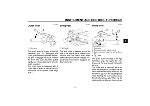 29
29 30
30 31
31 32
32 33
33 34
34 35
35 36
36 37
37 38
38 39
39 40
40 41
41 42
42 43
43 44
44 45
45 46
46 47
47 48
48 49
49 50
50 51
51 52
52 53
53 54
54 55
55 56
56 57
57 58
58 59
59 60
60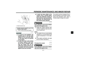 61
61 62
62 63
63 64
64 65
65 66
66 67
67 68
68 69
69 70
70 71
71 72
72 73
73 74
74 75
75 76
76 77
77 78
78 79
79 80
80 81
81 82
82 83
83 84
84 85
85 86
86 87
87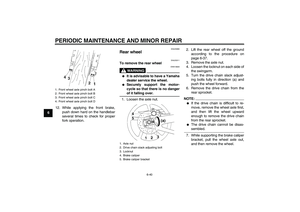 88
88 89
89 90
90 91
91 92
92 93
93 94
94 95
95 96
96 97
97 98
98 99
99 100
100 101
101 102
102 103
103