Page 97 of 104

2nd:
33/16 (2.063)
3rd:
37/21 (1.762)
4th:
35/23 (1.522)
5th:
30/22 (1.364)
6th:
33/26 (1.269)Chassis:Frame type:
Diamond
Caster angle:
24.00 °
Tra")
SPECIFICATIONS
8-2
8
Gear ratio:
1st:
38/15 (2.533)
2nd:
33/16 (2.063)
3rd:
37/21 (1.762)
4th:
35/23 (1.522)
5th:
30/22 (1.364)
6th:
33/26 (1.269)Chassis:Frame type:
Diamond
Caster angle:
24.00 °
Trail:
97.0 mm (3.82 in)Front tire:Type:
Tubeless
Size:
120/70 ZR17M/C (58W)
Manufacturer/model:
MICHELIN/Pilot POWER C
Manufacturer/model:
DUNLOP/D218FLRear tire:Type:
Tubeless
Size:
190/50 ZR17M/C (73W)Manufacturer/model:
MICHELIN/Pilot POWER G
Manufacturer/model:
DUNLOP/D218L
Loading:Maximum load:
202 kg (445 lb)
(Total weight of rider, passenger, cargo and
accessories)Tire air pressure (measured on cold
tires):Loading condition:
0–90 kg (0–198 lb)
Front:
250 kPa (36 psi) (2.50 kgf/cm²)
Rear:
290 kPa (42 psi) (2.90 kgf/cm²)
Loading condition:
90–202 kg (198–445 lb)
Front:
250 kPa (36 psi) (2.50 kgf/cm²)
Rear:
290 kPa (42 psi) (2.90 kgf/cm²)
High-speed riding:
Front:
250 kPa (36 psi) (2.50 kgf/cm²)
Rear:
290 kPa (42 psi) (2.90 kgf/cm²)Front wheel:Wheel type:
Cast wheel
Rim size:
17M/C x MT3.50
Rear wheel:Wheel type:
Cast wheel
Rim size:
17M/C x MT6.00Front brake:Type:
Dual disc brake
Operation:
Right hand operation
Recommended fluid:
DOT 4Rear brake:Type:
Single disc brake
Operation:
Right foot operation
Recommended fluid:
DOT 4Front suspension:Type:
Telescopic fork
Spring/shock absorber type:
Coil spring/oil damper
Wheel travel:
120.0 mm (4.72 in)Rear suspension:Type:
Swingarm (link suspension)
Spring/shock absorber type:
Coil spring/gas-oil damper
Wheel travel:
130.0 mm (5.12 in)
U5VYE1E0.book Page 2 Tuesday, September 7, 2004 9:09 AM
Page 98 of 104

Charging system:
AC magnetoBattery:Model:
YTZ10S
Voltage, capacity:
12 V, 8.6 AhHeadlight:Bulb type:
Halo")
SPECIFICATIONS
8-3
8
Electrical system:Ignition system:
Transistorized coil ignition (digital)
Charging system:
AC magnetoBattery:Model:
YTZ10S
Voltage, capacity:
12 V, 8.6 AhHeadlight:Bulb type:
Halogen bulbBulb voltage, wattage x quantity:Headlight:
12 V, 55.0 W × 4
Tail/brake light:
LED
Front turn signal light:
12 V, 10.0 W × 2
Rear turn signal light:
12 V, 10.0 W × 2
Auxiliary light:
12 V, 5.0 W × 2
Licence plate light:
12 V, 5.0 W × 1
Meter lighting:
LED
Neutral indicator light:
LED
High beam indicator light:
LED
Oil level warning light:
LEDTurn signal indicator light:
LED
Fuel level warning light:
LED
Engine trouble warning light:
LED
Coolant temperature warning light:
LED
Immobilizer system indicator light:
LED
Shift timing indicator light:
LED
Fuses:Main fuse:
50.0 A
Headlight fuse:
25.0 A
Signaling system fuse:
10.0 A
Ignition fuse:
15.0 A
Radiator fan fuse:
15.0 A × 2
Turn signal light fuse:
10.0 A
Electronic fuel injection fuse:
15.0 A
Backup fuse:
10.0 A
U5VYE1E0.book Page 3 Tuesday, September 7, 2004 9:09 AM
Page 99 of 104

CONSUMER INFORMATION
9-1
9
EAU26351
Identification numbers Record the key identification number,
vehicle identification number and mod-
el label information in the spaces pro-
vided below for assistance when
ordering spare parts from a Yamaha
dealer or for reference in case the vehi-
cle is stolen.
KEY IDENTIFICATION NUMBER:
VEHICLE IDENTIFICATION
NUMBER:
MODEL LABEL INFORMATION:
EAU26381
Key identification number
The key identification number is
stamped into the key tag. Record this
number in the space provided and use
it for reference when ordering a new
key.
EAU26400
Vehicle identification number
The vehicle identification number is
stamped into the steering head pipe.
Record this number in the space pro-
vided.NOTE:
The vehicle identification number is
used to identify your motorcycle and
may be used to register your motor-
cycle with the licensing authority in yourarea.
1. Key identification number
2. Code re-registering key (red bow)
3. Standard keys (black bow)
1. Vehicle identification number
U5VYE1E0.book Page 1 Tuesday, September 7, 2004 9:09 AM
Page 100 of 104
CONSUMER INFORMATION
9-2
9
EAU33941
Model label
The model label is affixed to the frame
under the passenger seat. (See page
3-19.) Record the information on this la-
bel in the space provided. This informa-
tion will be needed when ordering
spare parts from a Yamaha dealer.
WARNING
EWA12371
Do not touch either muffler bracket,
located under the muffler bracket
covers, until the exhaust system hascooled.1. Model label
1. Muffler bracket cover
2. Muffler bracket
U5VYE1E0.book Page 2 Tuesday, September 7, 2004 9:09 AM
Page 101 of 104
 ..................... 3-13
Auxiliary light bulb, replacing ................ 6-36BBattery .....................")
INDEX
AAir filter element, replacing ................... 6-14
Anti-theft alarm (optional) ..................... 3-13
Auxiliary light bulb, replacing ................ 6-36BBattery .................................................. 6-29
Brake and clutch levers,
checking and lubricating ..................... 6-26
Brake fluid, changing ............................ 6-23
Brake fluid level, checking .................... 6-22
Brake lever ........................................... 3-15
Brake pedal .......................................... 3-16CCables, checking and lubricating .......... 6-25
Care ........................................................ 7-1
Catalytic converter ................................ 3-18
Clutch lever........................................... 3-15
Clutch lever free play, adjusting ........... 6-20
Coolant ................................................. 6-12
Coolant temperature warning light.......... 3-4DDimmer switch ...................................... 3-14
Drive chain, lubricating ......................... 6-24
Drive chain slack .................................. 6-23EEngine break-in ...................................... 5-3
Engine idling speed .............................. 6-16
Engine oil and oil filter cartridge ............. 6-8
Engine stop switch................................ 3-14
Engine trouble warning light ................... 3-7
EXUP system ....................................... 3-25FFront and rear brake pads, checking .... 6-21
Front fork, adjusting .............................. 3-20Front fork, checking...............................6-27
Fuel ....................................................... 3-17
Fuel consumption, tips for reducing ........ 5-3
Fuel level warning light............................ 3-4
Fuel tank breather/overflow hose .......... 3-18
Fuel tank cap......................................... 3-16
Fuses, replacing .................................... 6-30
HHandlebar switches ............................... 3-13
Hazard switch........................................ 3-14
Headlight bulb, replacing....................... 6-32
Helmet holders ...................................... 3-20
High beam indicator light......................... 3-4
Horn switch ........................................... 3-14IIdentification numbers ............................. 9-1
Ignition circuit cut-off system ................. 3-26
Immobilizer system .................................3-1
Immobilizer system indicator light ........... 3-7
Indicator and warning lights .................... 3-3KKey identification number ........................ 9-1LLicense plate light bulb, replacing ......... 6-36
Luggage strap holders .......................... 3-24MMain switch/steering lock ........................ 3-2
Model label .............................................. 9-2
Multi-function meter unit .......................... 3-8NNeutral indicator light .............................. 3-4OOil level warning light .............................. 3-4
PPanels, removing and installing .............. 6-6
Parking.................................................... 5-4
Part locations .......................................... 2-1
Pass switch ........................................... 3-14
Periodic maintenance and
lubrication chart .................................... 6-2
Pre-operation check list .......................... 4-2RRear brake light switch, adjusting ......... 6-21SSafety information ................................... 1-1
Seats..................................................... 3-19
Shifting .................................................... 5-2
Shift pedal ............................................. 3-15
Shift timing indicator light ........................ 3-7
Shock absorber assembly, adjusting .... 3-22
Sidestand .............................................. 3-25
Sidestand, checking and lubricating ..... 6-26
Spark plugs, checking............................. 6-7
Specifications.......................................... 8-1
Starting the engine.................................. 5-1
Start switch ........................................... 3-14
Steering, checking ................................ 6-28
Storage ................................................... 7-3
Supporting the motorcycle .................... 6-37
Swingarm pivots, lubricating ................. 6-27TTail/brake light ...................................... 6-35
Throttle cable free play, checking ......... 6-16
Throttle grip and cable,
checking and lubricating ..................... 6-25
Tires ...................................................... 6-17
Tool kit .................................................... 6-1
U5VYE1E0.book Page 1 Tuesday, September 7, 2004 9:09 AM
Page 102 of 104
INDEXTroubleshooting .................................... 6-41
Troubleshooting charts ......................... 6-42
Turn signal indicator lights ...................... 3-3
Turn signal light bulb, replacing ............ 6-35
Turn signal switch ................................. 3-14VValve clearance .................................... 6-17
Vehicle identification number .................. 9-1WWheel bearings, checking ..................... 6-28
Wheel (front) ......................................... 6-38
Wheel (rear) .......................................... 6-40
Wheels .................................................. 6-20
U5VYE1E0.book Page 2 Tuesday, September 7, 2004 9:09 AM
Page 103 of 104
U5VYE1E0.book Page 3 Tuesday, September 7, 2004 9:09 AM
Page 104 of 104
PRINTED ON RECYCLED PAPER
YAMAHA MOTOR CO., LTD.
PRINTED IN JAPAN
2004.09-0.8×1 CR
(E)5VY-28199-E1
YZF-R1
OWNER’S MANUAL
 1
1 2
2 3
3 4
4 5
5 6
6 7
7 8
8 9
9 10
10 11
11 12
12 13
13 14
14 15
15 16
16 17
17 18
18 19
19 20
20 21
21 22
22 23
23 24
24 25
25 26
26 27
27 28
28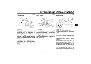 29
29 30
30 31
31 32
32 33
33 34
34 35
35 36
36 37
37 38
38 39
39 40
40 41
41 42
42 43
43 44
44 45
45 46
46 47
47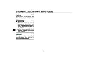 48
48 49
49 50
50 51
51 52
52 53
53 54
54 55
55 56
56 57
57 58
58 59
59 60
60 61
61 62
62 63
63 64
64 65
65 66
66 67
67 68
68 69
69 70
70 71
71 72
72 73
73 74
74 75
75 76
76 77
77 78
78 79
79 80
80 81
81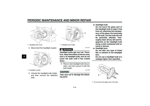 82
82 83
83 84
84 85
85 86
86 87
87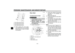 88
88 89
89 90
90 91
91 92
92 93
93 94
94 95
95 96
96 97
97 98
98 99
99 100
100 101
101 102
102 103
103 Record the information on this la-
bel in the space provided. This i")


5VY-28199-E1
YZF-R1
OWNER’S MANUAL")