Page 81 of 104

PERIODIC MAINTENANCE AND MINOR REPAIR
6-33
6 2. Unhook the headlight bulb holder,
and then remove the defective
bulb.
WARNING
EWA10790
Headlight bulbs get very hot. There-
fore, keep flammable products away
from a lit headlight bulb, and do not
touch the bulb until it has cooleddown.
3. Place a new headlight bulb into po-
sition, and then secure it with the
bulb holder.CAUTION:
ECA10650
Take care not to damage the follow-
ing parts:�
Headlight bulb
Do not touch the glass part of
the headlight bulb to keep it free
from oil, otherwise the transpar-
ency of the glass, the luminosity
of the bulb, and the bulb life will
be adversely affected. Thor-
oughly clean off any dirt and fin-
gerprints on the headlight bulb
using a cloth moistened with al-
cohol or thinner.
�
Headlight lens
Do not affix any type of tinted
film or stickers to the headlight
lens.
Do not use a headlight bulb of awattage higher than specified.
4. Install the headlight bulb cover,
and then connect the coupler.
5. Have a Yamaha dealer adjust the
headlight beam if necessary.
To replace a low beam headlight
bulb
1. Remove the headlight bulb cover
by turning it counterclockwise.
1. Headlight bulb cover
2. Headlight coupler
1. Headlight bulb holder
1. Do not touch the glass part of the bulb.
U5VYE1E0.book Page 33 Tuesday, September 7, 2004 9:09 AM
Page 82 of 104

PERIODIC MAINTENANCE AND MINOR REPAIR
6-34
62. Disconnect the headlight coupler.
3. Unhook the headlight bulb holder,
and then remove the defective
bulb.
WARNING
EWA10790
Headlight bulbs get very hot. There-
fore, keep flammable products away
from a lit headlight bulb, and do not
touch the bulb until it has cooleddown.
4. Place a new headlight bulb into po-
sition, and then secure it with the
bulb holder.CAUTION:
ECA10650
Take care not to damage the follow-
ing parts:
�
Headlight bulb
Do not touch the glass part of
the headlight bulb to keep it free
from oil, otherwise the transpar-
ency of the glass, the luminosity
of the bulb, and the bulb life will
be adversely affected. Thor-
oughly clean off any dirt and fin-
gerprints on the headlight bulb
using a cloth moistened with al-
cohol or thinner.
�
Headlight lens
Do not affix any type of tinted
film or stickers to the headlight
lens.
Do not use a headlight bulb of awattage higher than specified.
1. Headlight bulb cover
1. Headlight coupler
1. Headlight bulb holder
1. Do not touch the glass part of the bulb.
U5VYE1E0.book Page 34 Tuesday, September 7, 2004 9:09 AM
Page 83 of 104
PERIODIC MAINTENANCE AND MINOR REPAIR
6-35
6 5. Connect the headlight coupler.
6. Install the headlight bulb cover by
turning it clockwise.
7. Have a Yamaha dealer adjust the
headlight beam if necessary.
EAU24180
Tail/brake light This model is equipped with an LED
type of tail/brake light.
If the tail/brake light does not come on,
have a Yamaha dealer check it.
EAU24201
Replacing a turn signal light
bulb 1. Remove the turn signal light lens
by removing the screw.
2. Remove the defective bulb by
pushing it in and turning it counter-
clockwise.
3. Insert a new bulb into the socket,
push it in, and then turn it clock-
wise until it stops.
4. Install the lens by installing the
screw.CAUTION:
ECA11190
Do not overtighten the screw, other-wise the lens may break.1. Screw
U5VYE1E0.book Page 35 Tuesday, September 7, 2004 9:09 AM
Page 84 of 104

PERIODIC MAINTENANCE AND MINOR REPAIR
6-36
6
EAU24310
Replacing the license plate
light bulb 1. Remove the license plate light unit
by removing the screws.
2. Remove the socket (together with
the bulb) by pulling it out.3. Remove the defective bulb by pull-
ing it out.
4. Insert a new bulb into the socket.
5. Install the socket (together with the
bulb) by pushing it in.
6. Install the license plate light unit by
installing the screws.
EAU33910
Replacing an auxiliary light
bulb This model is equipped with two auxil-
iary lights. If an auxiliary light bulb burns
out, replace it as follows.
1. Remove panel A (if replacing the
left auxiliary light bulb) or panel C
(if replacing the right auxiliary light
bulb). (See page 6-6.)
2. Remove the auxiliary light bulb
cover by removing the quick fas-
tener.NOTE:
Remove the quick fastener by pushing
the center pin in with a screwdriver,then pulling the fastener out.
1. Screw
2. License plate light unit
1. License plate light bulb
1. Quick fastener
2. Auxiliary light bulb cover
U5VYE1E0.book Page 36 Tuesday, September 7, 2004 9:09 AM
Page 85 of 104
 by pulling it out.
4. Remove the defective bulb by pull-
ing it out.
5. Insert a new bulb into the socket.
6.")
PERIODIC MAINTENANCE AND MINOR REPAIR
6-37
6 3. Remove the socket (together with
the bulb) by pulling it out.
4. Remove the defective bulb by pull-
ing it out.
5. Insert a new bulb into the socket.
6. Install the socket (together with the
bulb) by pushing it in.7. Install the auxiliary light bulb cover
by installing the quick fastener.
NOTE:To install the quick fastener, push the
center pin out so that it will protrude
from the fastener head, insert the fas-
tener into the auxiliary light bulb cover,
and then push the protruding pin in untilit is flush with the fastener head.
8. Install the panel.
EAU24350
Supporting the motorcycle Since this model is not equipped with a
centerstand, follow these precautions
when removing the front and rear
wheel or performing other maintenance
requiring the motorcycle to stand up-
right. Check that the motorcycle is in a
stable and level position before starting
any maintenance. A strong wooden
box can be placed under the engine for
added stability.
To service the front wheel
1. Stabilize the rear of the motorcycle
by using a motorcycle stand or, if
an additional motorcycle stand is
not available, by placing a jack un-
der the frame in front of the rear
wheel.
2. Raise the front wheel off the
ground by using a motorcycle
stand.
To service the rear wheel
Raise the rear wheel off the ground by
using a motorcycle stand or, if a motor-
cycle stand is not available, by placing
1. Auxiliary light bulb socket
1. Auxiliary light bulb
U5VYE1E0.book Page 37 Tuesday, September 7, 2004 9:09 AM
Page 86 of 104
PERIODIC MAINTENANCE AND MINOR REPAIR
6-38
6a jack either under each side of the
frame in front of the rear wheel or under
each side of the swingarm.
EAU24360
Front wheel
EAU33921
To remove the front wheel
WARNING
EWA10820
�
It is advisable to have a Yamaha
dealer service the wheel.
�
Securely support the motor-
cycle so that there is no dangerof it falling over.
1. Loosen the wheel axle pinch bolts,
the axle bolt, and then the brake
caliper bolts.
2. Lift the front wheel off the ground
according to the procedure on
page 6-37.3. Remove the brake hose holder on
each side by removing the bolt and
nut.
4. Remove the brake caliper on each
side by removing the bolts.
5. Remove the axle bolt, push the
wheel axle out from the left side,
and then remove the wheel.
1. Front wheel axle pinch bolt
1. Brake hose holder
2. Bolt and nut
3. Brake caliper bolt
4. Brake caliper
5. Axle bolt
U5VYE1E0.book Page 38 Tuesday, September 7, 2004 9:09 AM
Page 87 of 104

PERIODIC MAINTENANCE AND MINOR REPAIR
6-39
6
CAUTION:
ECA11050
Do not apply the brake after the
brake calipers have been removed,
otherwise the brake pads will beforced shut.
EAU33931
To install the front wheel
1. Lift the wheel up between the fork
legs.
2. Insert the wheel axle.
3. Lower the front wheel so that it is
on the ground.
4. Install the brake calipers by install-
ing the bolts, and then tightening
them to the specified torque.
NOTE:Make sure that there is enough space
between the brake pads before install-
ing the brake calipers onto the brakediscs.
5. Install the brake hose holders by
installing the bolts and nuts.
6. Secure the wheel axle by installing
the axle bolt, and then tightening
the axle bolt to the specified
torque.NOTE:While tightening the axle bolt, hold the
wheel axle with a 19-mm hexagonwrench to keep it from turning.
7. Tighten wheel axle pinch bolt B,
and then tighten pinch bolt A to the
specified torque.8. Retighten pinch bolt B to the spec-
ified torque.
9. Tap the outer side of the right fork
leg with a rubber mallet to align it
with the end of the wheel axle.
10. Tighten wheel axle pinch bolt D,
and then tighten pinch bolt C to the
specified torque.
11. Retighten pinch bolt D to the spec-
ified torque.
1. Wheel axle
Tightening torque:
Brake caliper bolt:
35 Nm (3.5 m·kgf, 25 ft·lbf)
Tightening torque:
Axle bolt:
91 Nm (9.1 m·kgf, 66 ft·lbf)
Tightening torque:
Wheel axle pinch bolt:
21 Nm (2.1 m·kgf, 15 ft·lbf)
Tightening torque:
Wheel axle pinch bolt:
21 Nm (2.1 m·kgf, 15 ft·lbf)
U5VYE1E0.book Page 39 Tuesday, September 7, 2004 9:09 AM
Page 88 of 104

PERIODIC MAINTENANCE AND MINOR REPAIR
6-40
612. While applying the front brake,
push down hard on the handlebar
several times to check for proper
fork operation.
EAU25080
Rear wheel
EAU25311
To remove the rear wheel
WARNING
EWA10820
�
It is advisable to have a Yamaha
dealer service the wheel.
�
Securely support the motor-
cycle so that there is no dangerof it falling over.
1. Loosen the axle nut.2. Lift the rear wheel off the ground
according to the procedure on
page 6-37.
3. Remove the axle nut.
4. Loosen the locknut on each side of
the swingarm.
5. Turn the drive chain slack adjust-
ing bolts fully in direction (a) and
push the wheel forward.
6. Remove the drive chain from the
rear sprocket.
NOTE:�
If the drive chain is difficult to re-
move, remove the wheel axle first,
and then lift the wheel upward
enough to remove the drive chain
from the rear sprocket.
�
The drive chain cannot be disas-sembled.
7. While supporting the brake caliper
bracket, pull the wheel axle out,
and then remove the wheel.
1. Front wheel axle pinch bolt A
2. Front wheel axle pinch bolt B
3. Front wheel axle pinch bolt C
4. Front wheel axle pinch bolt D
1. Axle nut
2. Drive chain slack adjusting bolt
3. Locknut
4. Brake caliper
5. Brake caliper bracket
U5VYE1E0.book Page 40 Tuesday, September 7, 2004 9:09 AM
 1
1 2
2 3
3 4
4 5
5 6
6 7
7 8
8 9
9 10
10 11
11 12
12 13
13 14
14 15
15 16
16 17
17 18
18 19
19 20
20 21
21 22
22 23
23 24
24 25
25 26
26 27
27 28
28 29
29 30
30 31
31 32
32 33
33 34
34 35
35 36
36 37
37 38
38 39
39 40
40 41
41 42
42 43
43 44
44 45
45 46
46 47
47 48
48 49
49 50
50 51
51 52
52 53
53 54
54 55
55 56
56 57
57 58
58 59
59 60
60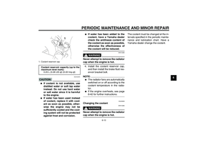 61
61 62
62 63
63 64
64 65
65 66
66 67
67 68
68 69
69 70
70 71
71 72
72 73
73 74
74 75
75 76
76 77
77 78
78 79
79 80
80 81
81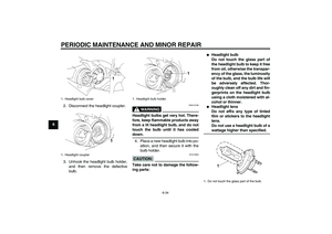 82
82 83
83 84
84 85
85 86
86 87
87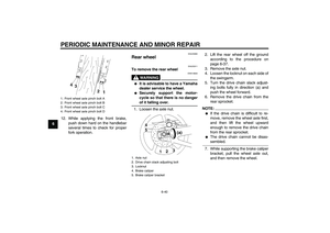 88
88 89
89 90
90 91
91 92
92 93
93 94
94 95
95 96
96 97
97 98
98 99
99 100
100 101
101 102
102 103
103
