Page 33 of 104

INSTRUMENT AND CONTROL FUNCTIONS
3-19
3
EAU33860
Seats Rider seat
To remove the rider seatPull back the rear of the rider seat as
shown, remove the bolts, and then pull
the seat off.
To install the rider seatInsert the projection on the front of the
rider seat into the seat holder as
shown, place the seat in the original po-
sition, and then install the bolts.Passenger seat
To remove the passenger seat
1. Insert the key into the seat lock,
and then turn it clockwise.2. While holding the key in that posi-
tion, lift the front of the passenger
seat and pull it forward.
To install the passenger seat
1. Insert the projection on the rear of
the passenger seat into the seat
holder as shown, and then push
the front of the seat down to lock it
in place.
2. Remove the key.NOTE:Make sure that the seats are properlysecured before riding.
1. Bolt
1. Projection
2. Seat holder
1. Passenger seat lock
2. Unlock.
1. Projection
2. Seat holder
U5VYE1E0.book Page 19 Tuesday, September 7, 2004 9:09 AM
Page 34 of 104

INSTRUMENT AND CONTROL FUNCTIONS
3-20
3
EAU33870
Helmet holders The helmet holders are located on the
bottom of the passenger seat.
To secure a helmet to a helmet hold-
er
1. Remove the passenger seat. (See
page 3-19.)
2. Attach the helmet to a helmet hold-
er, and then securely install the
passenger seat.
WARNING
EWA11040
Never ride with a helmet attached to
a helmet holder, since the helmet
may hit objects, causing loss of con-trol and possibly an accident.To release a helmet from a helmet
holder
Remove the passenger seat, remove
the helmet from the helmet holder, and
then install the seat.
EAU14741
Adjusting the front fork This front fork is equipped with spring
preload adjusting bolts, rebound damp-
ing force adjusting screws and com-
pression damping force adjusting
screws.
WARNING
EWA10180
Always adjust both fork legs equal-
ly, otherwise poor handling and lossof stability may result.
Spring preload
To increase the spring preload and
thereby harden the suspension, turn
the adjusting bolt on each fork leg in di-
rection (a). To decrease the spring pre-
1. Helmet holder
1. Spring preload adjusting bolt
U5VYE1E0.book Page 20 Tuesday, September 7, 2004 9:09 AM
Page 35 of 104
.
NOTE:Align the appropriate groove on the ad-
justing mechanis")
INSTRUMENT AND CONTROL FUNCTIONS
3-21
3 load and thereby soften the
suspension, turn the adjusting bolt on
each fork leg in direction (b).
NOTE:Align the appropriate groove on the ad-
justing mechanism with the top of thefront fork cap bolt.Rebound damping force
To increase the rebound damping force
and thereby harden the rebound damp-
ing, turn the adjusting screw on each
fork leg in direction (a). To decrease the
rebound damping force and thereby
soften the rebound damping, turn the
adjusting screw on each fork leg in di-
rection (b).Compression damping force
To increase the compression damping
force and thereby harden the compres-
sion damping, turn the adjusting screw
on each fork leg in direction (a). To de-
crease the compression damping force
and thereby soften the compression
damping, turn the adjusting screw on
each fork leg in direction (b).1. Current setting
2. Front fork cap boltSpring preload setting:
Minimum (soft):
8
Standard:
4.5
Maximum (hard):
0
1. Rebound damping force adjusting screw
Rebound damping setting:
Minimum (soft):
26 click(s) in direction (b)*
Standard:
10 click(s) in direction (b)*
Maximum (hard):
1 click(s) in direction (b)*
* With the adjusting screw fully turned
in direction (a)
1. Compression damping force adjusting screw
Compression damping setting:
Minimum (soft):
25 click(s) in direction (b)*
Standard:
10 click(s) in direction (b)*
Maximum (hard):
1 click(s) in direction (b)*
* With the adjusting screw fully turned
in direction (a)
U5VYE1E0.book Page 21 Tuesday, September 7, 2004 9:09 AM
Page 36 of 104

INSTRUMENT AND CONTROL FUNCTIONS
3-22
3
CAUTION:
ECA10100
Never attempt to turn an adjusting
mechanism beyond the maximum orminimum settings.NOTE:Although the total number of clicks of a
damping force adjusting mechanism
may not exactly match the above spec-
ifications due to small differences in
production, the actual number of clicks
always represents the entire adjusting
range. To obtain a precise adjustment,
it would be advisable to check the num-
ber of clicks of each damping force ad-
justing mechanism and to modify thespecifications as necessary.
EAU33970
Adjusting the shock absorber
assembly This shock absorber assembly is
equipped with a spring preload adjust-
ing ring and rebound and compression
damping force adjusting screws.CAUTION:
ECA10100
Never attempt to turn an adjusting
mechanism beyond the maximum orminimum settings.
Spring preloadTo increase the spring preload and
thereby harden the suspension, turn
the adjusting ring in direction (a). To de-
crease the spring preload and thereby
soften the suspension, turn the adjust-
ing ring in direction (b).
NOTE:�
Align the appropriate notch in the
adjusting ring with the position in-
dicator on the shock absorber.
�
Use the special wrench included in
the owner’s tool kit to make the ad-justment.
Rebound damping force
Adjust the rebound damping force as
follows.
1. Remove the bolt, loosen and re-
move the quick fastener screw,
and then pull the cowling away
from the motorcycle as shown.
1. Special wrench
2. Spring preload adjusting ring
3. Position indicator
Spring preload setting:
Minimum (soft):
1
Standard:
4
Maximum (hard):
9
U5VYE1E0.book Page 22 Tuesday, September 7, 2004 9:09 AM
Page 37 of 104
. To decrease
the rebound damping fo")
INSTRUMENT AND CONTROL FUNCTIONS
3-23
3
2. To increase the rebound damping
force and thereby harden the re-
bound damping, turn the adjusting
screw in direction (a). To decrease
the rebound damping force and
thereby soften the rebound damp-
ing, turn the adjusting screw in di-
rection (b). 3. Place the cowling in its original po-
sition, install and tighten the quick
fastener screw, and then install the
bolt.Compression damping force
To increase the compression damping
force and thereby harden the compres-
sion damping, turn the adjusting screw
in direction (a). To decrease the com-
pression damping force and thereby
soften the compression damping, turn
the adjusting screw in direction (b).
1. Quick fastener screw
2. Bolt
3. Cowling
1. Rebound damping force adjusting screw
Rebound damping setting:
Minimum (soft):
20 click(s) in direction (b)*
Standard:
17 click(s) in direction (b)*
Maximum (hard):
1 click(s) in direction (b)*
* With the adjusting screw fully turned
in direction (a)
1. Compression damping force adjusting screw
Compression damping setting:
Minimum (soft):
20 click(s) in direction (b)*
Standard:
12 click(s) in direction (b)*
Maximum (hard):
1 click(s) in direction (b)*
* With the adjusting screw fully turned
in direction (a)
U5VYE1E0.book Page 23 Tuesday, September 7, 2004 9:09 AM
Page 38 of 104

INSTRUMENT AND CONTROL FUNCTIONS
3-24
3
NOTE:Although the total number of clicks of a
damping force adjusting mechanism
may not exactly match the specifica-
tions listed due to small differences in
production, the actual number of clicks
always represents the entire adjust-
ment range. To obtain a precise adjust-
ment, it would be advisable to check
the number of clicks of each damping
force adjusting mechanism and to mod-ify the specifications as necessary.
WARNING
EWA10220
This shock absorber contains highly
pressurized nitrogen gas. For prop-
er handling, read and understand
the following information before
handling the shock absorber. The
manufacturer cannot be held re-
sponsible for property damage or
personal injury that may result from
improper handling.�
Do not tamper with or attempt to
open the gas cylinder.
�
Do not subject the shock ab-
sorber to an open flame or other
high heat sources, otherwise it
may explode due to excessive
gas pressure.
�
Do not deform or damage the
gas cylinder in any way, as this
will result in poor damping per-
formance.
�
Always have a Yamaha dealerservice the shock absorber.
EAU15181
Luggage strap holders There are four luggage strap holders on
the bottom of the passenger seat. To
use the strap holders, remove the pas-
senger seat, unhook the straps from
the hooks, and then install the seat with
the straps hanging out from under the
passenger seat. (See page 3-19.)1. Luggage strap holder
2. Hook
U5VYE1E0.book Page 24 Tuesday, September 7, 2004 9:09 AM
Page 39 of 104

system. This system boosts engine
power by means of a valve that")
INSTRUMENT AND CONTROL FUNCTIONS
3-25
3
EAU15281
EXUP system This model is equipped with Yamaha’s
EXUP (EXhaust Ultimate Power valve)
system. This system boosts engine
power by means of a valve that regu-
lates the diameter of the exhaust pipe.
The EXUP system valve is constantly
adjusted in accordance with the engine
speed by a computer-controlled servo-
motor.CAUTION:
ECA10191
�
The EXUP system has been set
and extensively tested at the
Yamaha factory. Changing
these settings without sufficient
technical knowledge may result
in poor performance of or dam-
age to the engine.
�
If the EXUP system cannot be
heard when the main switch is
turned on, have a Yamaha deal-er check it.
EAU15300
Sidestand The sidestand is located on the left side
of the frame. Raise the sidestand or
lower it with your foot while holding the
vehicle upright.NOTE:The built-in sidestand switch is part of
the ignition circuit cut-off system, which
cuts the ignition in certain situations.
(See further down for an explanation ofthe ignition circuit cut-off system.)
WARNING
EWA10240
The vehicle must not be ridden with
the sidestand down, or if the side-
stand cannot be properly moved up
(or does not stay up), otherwise the
sidestand could contact the ground
and distract the operator, resulting
in a possible loss of control.
Yamaha’s ignition circuit cut-off
system has been designed to assist
the operator in fulfilling the respon-
sibility of raising the sidestand be-
fore starting off. Therefore, check
this system regularly as describedbelow and have a Yamaha dealer re-
pair it if it does not function proper-
ly.
U5VYE1E0.book Page 25 Tuesday, September 7, 2004 9:09 AM
Page 40 of 104
INSTRUMENT AND CONTROL FUNCTIONS
3-26
3
EAU15311
Ignition circuit cut-off system The ignition circuit cut-off system (com-
prising the sidestand switch, clutch
switch and neutral switch) has the fol-
lowing functions.�
It prevents starting when the trans-
mission is in gear and the side-
stand is up, but the clutch lever is
not pulled.
�
It prevents starting when the trans-
mission is in gear and the clutch le-
ver is pulled, but the sidestand is
still down.
�
It cuts the running engine when the
transmission is in gear and the sid-
estand is moved down.
Periodically check the operation of the
ignition circuit cut-off system according
to the following procedure.WARNING
EWA10250
If a malfunction is noted, have a
Yamaha dealer check the system be-fore riding.U5VYE1E0.book Page 26 Tuesday, September 7, 2004 9:09 AM
 1
1 2
2 3
3 4
4 5
5 6
6 7
7 8
8 9
9 10
10 11
11 12
12 13
13 14
14 15
15 16
16 17
17 18
18 19
19 20
20 21
21 22
22 23
23 24
24 25
25 26
26 27
27 28
28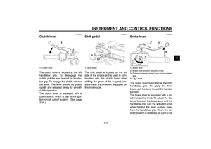 29
29 30
30 31
31 32
32 33
33 34
34 35
35 36
36 37
37 38
38 39
39 40
40 41
41 42
42 43
43 44
44 45
45 46
46 47
47 48
48 49
49 50
50 51
51 52
52 53
53 54
54 55
55 56
56 57
57 58
58 59
59 60
60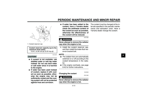 61
61 62
62 63
63 64
64 65
65 66
66 67
67 68
68 69
69 70
70 71
71 72
72 73
73 74
74 75
75 76
76 77
77 78
78 79
79 80
80 81
81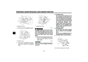 82
82 83
83 84
84 85
85 86
86 87
87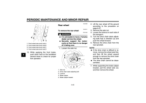 88
88 89
89 90
90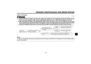 91
91 92
92 93
93 94
94 95
95 96
96 97
97 98
98 99
99 100
100 101
101 102
102 103
103 has the fol-")