Page 312 of 508
 4 - 57
ENG
Crankshaft
1. Install:
�Crankshaft 1
Use the crankshaft installing tool 2, 3, 4.
ÈFor USA and CDN
ÉExcept for USA and CDN
NOTE:
�Hold the connecting rod at top dead center
with one hand")
4 - 57
ENG
Crankshaft
1. Install:
�Crankshaft 1
Use the crankshaft installing tool 2, 3, 4.
ÈFor USA and CDN
ÉExcept for USA and CDN
NOTE:
�Hold the connecting rod at top dead center
with one hand while turning the nut of the
installing tool with the other. Operate the
installing tool until the crankshaft bottoms
against the bearing.
�Before installing the crankshaft, clean the
contacting surface of crankcase.
�Apply the lithium soap base grease on the oil
seal lip.
CAUTION:
Do not use a hammer to drive in the crank-
shaft.
Crankshaft installing pot 2:
YU-90050/90890-01274
Crankshaft installing bolt 3:
YU-90050/90890-01275
Adapter (M10) 4:
YM-1277/90890-01277
5PA41720
ÈÉ
5PA41730
2. Check:
�Shifter operation
�Transmission operation
Unsmooth operation → Repair.
3. Apply:
�Sealant
On the right crankcase 1.
NOTE:
Clean the contacting surface of left and right
crankcase before applying the sealant.
Quick gasket®:
ACC-QUICK-GS-KT
YAMAHA Bond No. 1215:
90890-85505
5PA41740
5PA41750
CRANKCASE AND CRANKSHAFT
Page 314 of 508
4 - 58
ENG
4. Install:
�Dowel pin 1
�Right crankcase 2
To left crankcase 3.
NOTE:
�Turn the shift cam 4 to the position shown in
the figure so that it does not contact the
crankcase when installing the crankcase.
�Fit the right crankcase onto the left crank-
case. Tap lightly on the case with soft ham-
mer.
�When installing the crankcase, the connect-
ing rod should be positioned at TDC (top
dead center).
5PA41760
5PA41770
5. Install:
�Clamp 1
�Screw (crankcase) 2
NOTE:
Tighten the crankcase tightening screws in
stage, using a crisscross pattern.
5PA41780
T R..8 Nm (0.8 m · kg, 5.8 ft · lb)
6. Install:
�Crankcase oil seal holder 1
�Bolt (crankcase oil seal holder) 2
7. Remove:
�Sealant
Forced out on the cylinder mating surface.
8. Apply:
�Engine oil
To the crank pin, bearing, oil delivery hole
and connecting rod end washer.
9. Check:
�Crankshaft and transmission operation
Unsmooth operation → Repair.
5PAR0010
T R..20 Nm (2.0 m · kg, 14 ft · lb)
CRANKCASE AND CRANKSHAFT
Page 316 of 508
4 - 59
ENG
EC4H0000
TRANSMISSION, SHIFT CAM AND SHIFT FORK
5PA41790
Extent of removal:
1 Shift cam and shift fork removal
2 Main axle and drive axle removal
Extent of removal Order Part name Q’ty Remarks
TRANSMISSION, SHIFT CAM
AND SHIFT FORK REMOVAL
Preparation for removal Engine Refer to “ENGINE REMOVAL” section.
Separate the crankcase. Refer to “CRANKCASE AND CRANK-
SHAFT” section.
1 Guide bar (long) 1
2 Guide bar (short) 1
3Shift cam 1
4 Shift fork 3 1
5 Shift fork 1 1
6 Shift fork 2 1
7 Main axle 1
Refer to “REMOVAL POINTS”.
8 Drive axle 1
9 Collar 1
1
2
TRANSMISSION, SHIFT CAM AND SHIFT FORK
Page 318 of 508
4 - 60
ENG
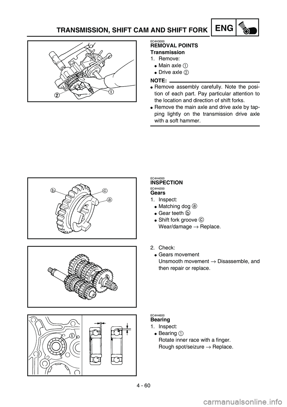
EC4H3000
REMOVAL POINTS
Transmission
1. Remove:
�Main axle 1
�Drive axle 2
NOTE:
�Remove assembly carefully. Note the posi-
tion of each part. Pay particular attention to
the location and direction of shift forks.
�Remove the main axle and drive axle by tap-
ping lightly on the transmission drive axle
with a soft hammer.
5PA41800
EC4H4000
INSPECTION
EC4H4200
Gears
1. Inspect:
�Matching dog a
�Gear teeth b
�Shift fork groove c
Wear/damage → Replace.
5PA41810
2. Check:
�Gears movement
Unsmooth movement → Disassemble, and
then repair or replace.
5PA41820
EC4H4600
Bearing
1. Inspect:
�Bearing 1
Rotate inner race with a finger.
Rough spot/seizure → Replace.
5PA41830
TRANSMISSION, SHIFT CAM AND SHIFT FORK
Page 320 of 508
4 - 61
ENG
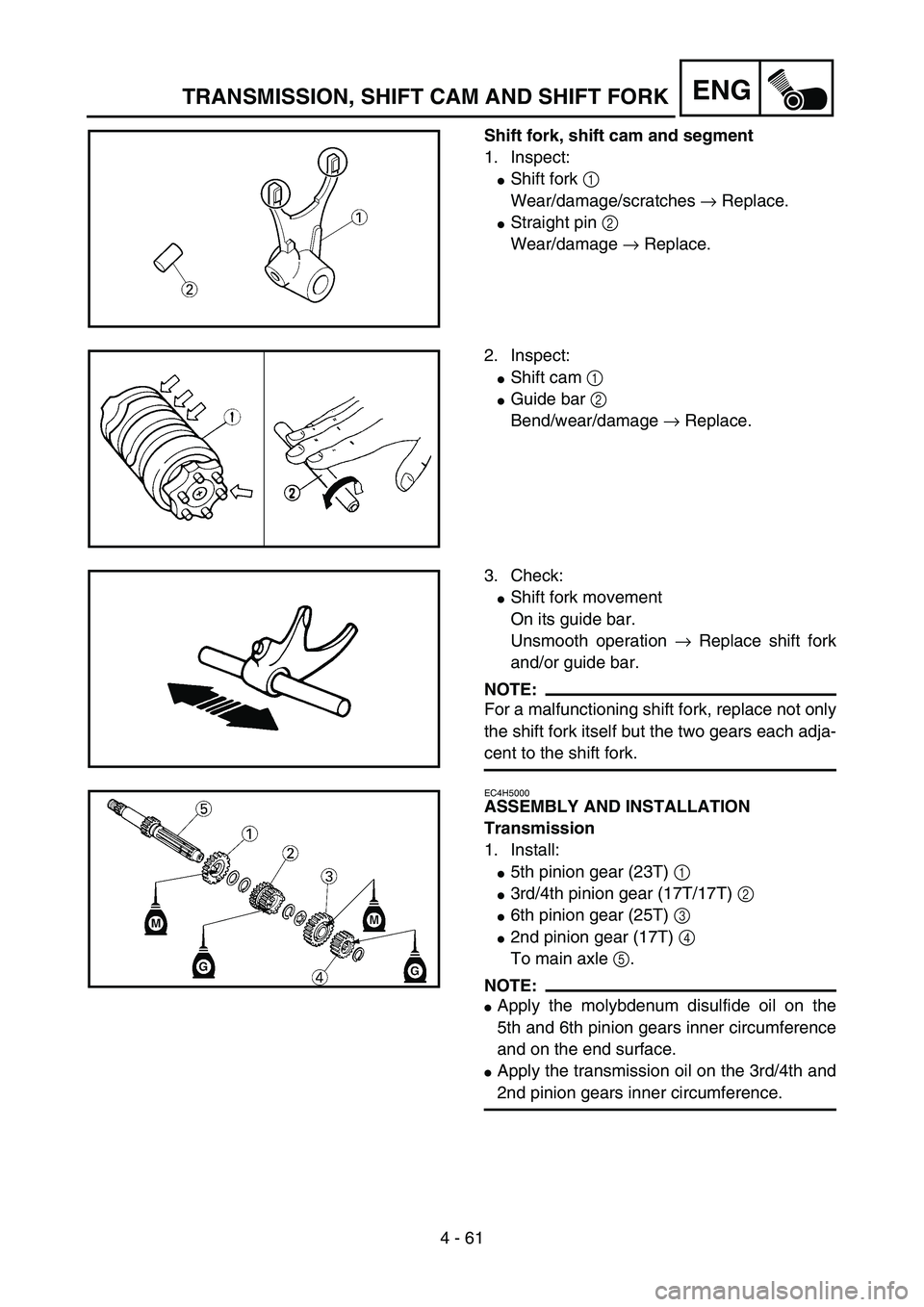
Shift fork, shift cam and segment
1. Inspect:
�Shift fork 1
Wear/damage/scratches → Replace.
�Straight pin 2
Wear/damage → Replace.
5PA41840
2. Inspect:
�Shift cam 1
�Guide bar 2
Bend/wear/damage → Replace.
5PA41850
3. Check:
�Shift fork movement
On its guide bar.
Unsmooth operation → Replace shift fork
and/or guide bar.
NOTE:
For a malfunctioning shift fork, replace not only
the shift fork itself but the two gears each adja-
cent to the shift fork.5PA41860
EC4H5000
ASSEMBLY AND INSTALLATION
Transmission
1. Install:
�5th pinion gear (23T) 1
�3rd/4th pinion gear (17T/17T) 2
�6th pinion gear (25T) 3
�2nd pinion gear (17T) 4
To main axle 5.
NOTE:
�Apply the molybdenum disulfide oil on the
5th and 6th pinion gears inner circumference
and on the end surface.
�Apply the transmission oil on the 3rd/4th and
2nd pinion gears inner circumference.
5PA41870
TRANSMISSION, SHIFT CAM AND SHIFT FORK
Page 322 of 508
4 - 62
ENG
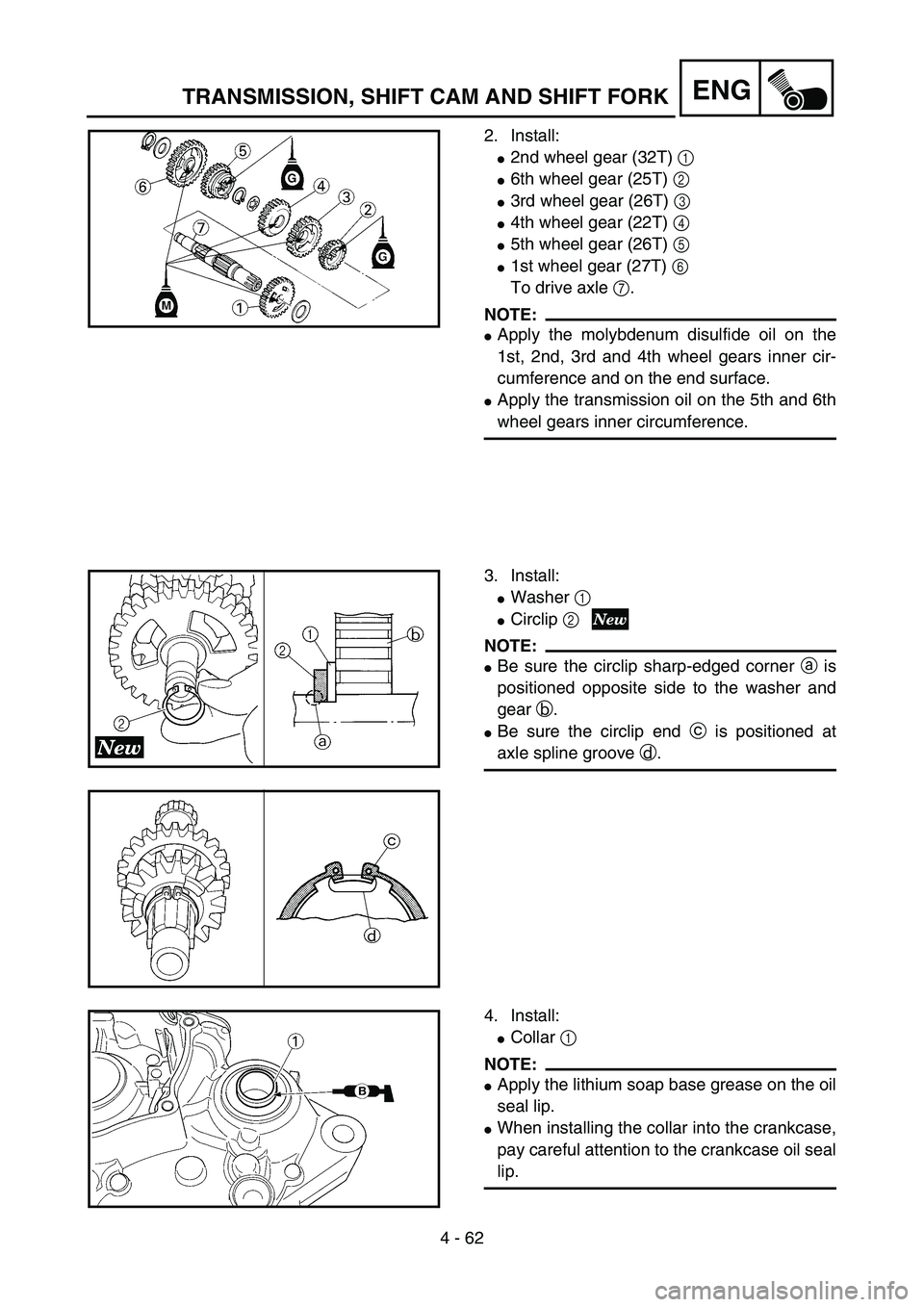
2. Install:
�2nd wheel gear (32T) 1
�6th wheel gear (25T) 2
�3rd wheel gear (26T) 3
�4th wheel gear (22T) 4
�5th wheel gear (26T) 5
�1st wheel gear (27T) 6
To drive axle 7.
NOTE:
�Apply the molybdenum disulfide oil on the
1st, 2nd, 3rd and 4th wheel gears inner cir-
cumference and on the end surface.
�Apply the transmission oil on the 5th and 6th
wheel gears inner circumference.
5PA41880
3. Install:
�Washer 1
�Circlip 2
NOTE:
�Be sure the circlip sharp-edged corner a is
positioned opposite side to the washer and
gear b.
�Be sure the circlip end c is positioned at
axle spline groove d.
5PA41900
5PA41890
4. Install:
�Collar 1
NOTE:
�Apply the lithium soap base grease on the oil
seal lip.
�When installing the collar into the crankcase,
pay careful attention to the crankcase oil seal
lip.
5PAR0011
TRANSMISSION, SHIFT CAM AND SHIFT FORK
Page 324 of 508
4 - 63
ENG
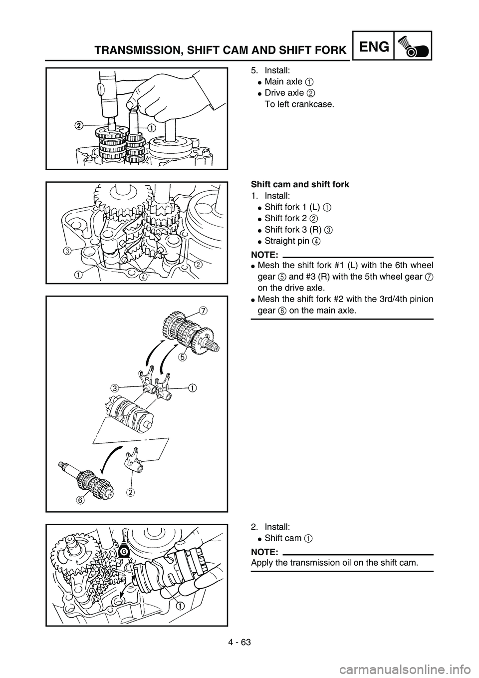
5. Install:
�Main axle 1
�Drive axle 2
To left crankcase.
5PA41920
Shift cam and shift fork
1. Install:
�Shift fork 1 (L) 1
�Shift fork 2 2
�Shift fork 3 (R) 3
�Straight pin 4
NOTE:
�Mesh the shift fork #1 (L) with the 6th wheel
gear 5 and #3 (R) with the 5th wheel gear 7
on the drive axle.
�Mesh the shift fork #2 with the 3rd/4th pinion
gear 6 on the main axle.
5PA41930
5PA41940
2. Install:
�Shift cam 1
NOTE:
Apply the transmission oil on the shift cam.
5PA41950
TRANSMISSION, SHIFT CAM AND SHIFT FORK
Page 326 of 508
4 - 64
ENG
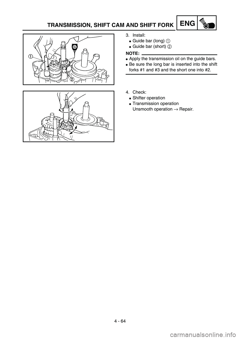
3. Install:
�Guide bar (long) 1
�Guide bar (short) 2
NOTE:
�Apply the transmission oil on the guide bars.
�Be sure the long bar is inserted into the shift
forks #1 and #3 and the short one into #2.
5PA41960
4. Check:
�Shifter operation
�Transmission operation
Unsmooth operation → Repair.
5PA41970
TRANSMISSION, SHIFT CAM AND SHIFT FORK

 4 - 59
ENG
EC4H0000
TRANSMISSION, SHIFT CAM AND SHIFT FORK
5PA41790
Extent of removal:
1 Shift cam and shift fork removal
2 Main axle and drive axle removal
Extent of removal Order Part name Q’ty Re")