Page 378 of 5135
A76869
Engine Room R/B No.1
Engine Room J/B No.1
EFI
12
1 1A1
B±G
4A
4B 11
Engine
Room J/B No.4
B±G
FL MAIN
Battery
EFBR B±Y
IE3
IO1 77
(LHD)(RHD)B±Y3
E9 BATTECM
E1 7
E12
A66054
Engine Room R/B No.1
EFI Fuse
05±262
± DIAGNOSTICSSFI SYSTEM (1AZ±FE)
AVENSIS REPAIR MANUAL (RM1018E)
ECM BACK±UP POWER SOURCE CIRCUIT
CIRCUIT DESCRIPTION
While the ignition switch is OFF, the battery positive voltage is supplied to terminal BATT of the ECM for the
DTCs memory and air±fuel ratio adaptive control value memory, etc.
WIRING DIAGRAM
INSPECTION PROCEDURE
1 CHECK FUSE(EFI FUSE)
(a) Remove the EFI fuse from the engine room R/B No.1.
(b) Check for continuity in the EFI fuse.
Standard: Continuity
NG CHECK FOR SHORT IN ALL HARNESSES AND
COMPONENTS CONNECTED FUSE
OK
05C78±01
Page 380 of 5135

A79123
I13
Ignition SW
4
6
IE4B±R
IP1 1
1(LHD)
B±R
11B±Y B±R
DHIGN
DA18 2Driver Side J/B
22
EFI
1 AM2
1
1A 1
B±GEngine Room
R/B No.1
Engine Room
J/B No.1 (RHD)
14A
14BEngine Room
J/B No.4
B±G
FL MAIN
BatteryB±W
(LHD)B±W
(LHD)
J8
J/C CC B±W
(RHD)B±W
(RHD)
J/C J26 J27AE
ECM
IGSW
E99
GR
IE12
GR
E98
MREL
44
51
EFI
Relay+B 1
E9 B±R
Engine Room
R/B No.4
Engine Room
R/B No.444
4
4E1 7
E12
IK1 8
1
2
EF ECW±B
B±RBR B±W
EFI
No.132
B±R
EA1 12
± DIAGNOSTICSSFI SYSTEM (1AZ±FE)
05±257
AVENSIS REPAIR MANUAL (RM1018E)
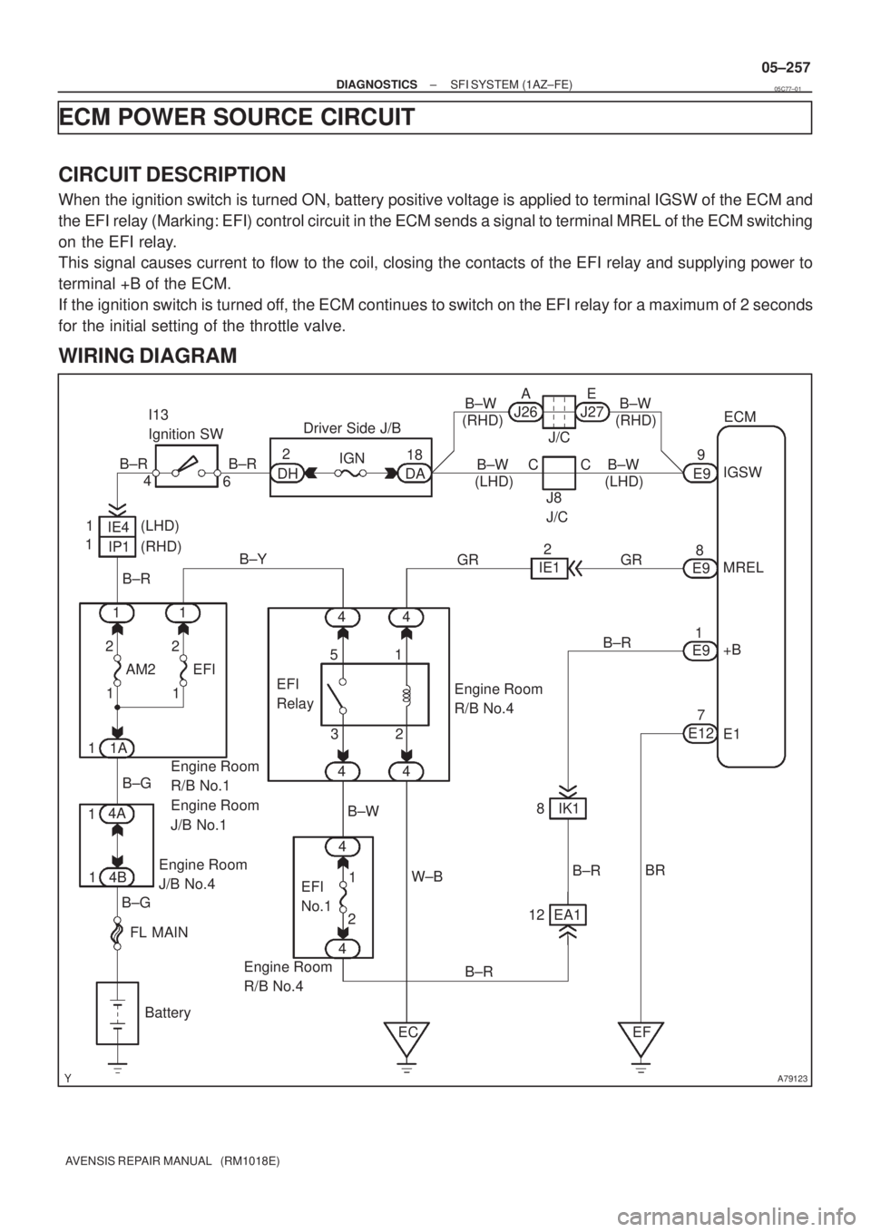
ECM POWER SOURCE CIRCUIT
CIRCUIT DESCRIPTION
When the ignition switch is turned ON, battery positive voltage is applied to terminal IGSW of the ECM and
the EFI relay (Marking: EFI) control circuit in the ECM sends a signal to terminal MREL of the ECM switching
on the EFI relay.
This signal causes current to flow to the coil, closing the contacts of the EFI relay and supplying power to
terminal +B of the ECM.
If the ignition switch is turned off, the ECM continues to switch on the EFI relay for a maximum of 2 seconds
for the initial setting of the throttle valve.
WIRING DIAGRAM
05C77±01
Page 388 of 5135
A76886
IE12
GRECM
MREL 8
E9
44
31
52A/F
Relay
Engine Room
R/B No.4 44
J12BR
D
J/C A/F 2
1
1A 11B±R
W±B Engine
Room
R/B No.1
Engine
Room
J/B No.1
EF ECBR J12 J/CJ13BR
D
EJ13
E B±G
Engine Room
J/B No.4 4A
4B 1 1
B±G
FL MAIN
BatteryW
W
GR
2EA11
EA1
W
W
2
4 A7
A/F Sensor
(Bank 1 Sensor 1)
1
36
E12 HA1A
23
E12 A1A+
31
E12A1A±
(*1)W
B L
A8
A/F Sensor
(Bank 2 Sensor 1)
5
E12 HA2A
22
E12 A2A+
30
E12A2A±
(*1) 2
41
3
L Y
G
*1: Shielded
± DIAGNOSTICSSFI SYSTEM (1AZ±FE)
05±251
AVENSIS REPAIR MANUAL (RM1018E)
WIRING DIAGRAM
Page 395 of 5135

A58697
Intake Air
Chamber
Throttle Valve
To Cylinder
ISC Valve
Valve
ECM
Signal From
Air
Cleaner
From
Terminal 2 of
EFI No.1 Fuse
(See Page 05±257)
A79101
2 +B DUTY1
GND 3
I10
ISC Valve
G±R10
E12 RSDECM
B±R 12
EA1 B±R
W±B7
E12 E1
BR
EF
±
DIAGNOSTICS SFI SYSTEM (1AZ±FE)
05±243
AVENSIS REPAIR MANUAL (RM1018E)
DTC P0511/33 IDLE AIR CONTROL CIRCUIT
CIRCUIT DESCRIPTION
The rotary solenoid type idle speed control (ISC) valve is lo-
cated under the throttle body and intake air bypassing the
throttle valve is directed to the idle speed control (ISC) valve
through the passage.
In this way the intake air volume bypassing the throttle valve is
regulated, controls the engine speed.
The ECM operates the idle speed control (ISC) valve only to
perform idle±up and provide feedback for the target idling
speed.
DTC No.DTC Detecting ConditionTrouble Area
P0511/33Idle speed continues to vary greatly from target speed
(1 trip detection logic)
�Open or short in idle speed control (ISC) valve circuit
� Idle speed control (ISC) valve is stuck or closed
� A/C switch circuit
� Air induction system
� ECM
WIRING DIAGRAM
INSPECTION PROCEDURE
HINT:
Read freeze frame data using \f�� �� ����\b� \f��\f�
� Freeze frame data records the engine conditions when
a malfunction is detected. When troubleshooting, it is useful for determi\
ning whether the vehicle was running
or stopped, the engine was warmed up or not, the air±fuel ratio was lea\
n or rich, etc. at the time of the mal-
function.
05C74±01
Page 400 of 5135
A76866
Combination MeterECM
C11 V±W
SPD
17
V±W E10
J/C
18H
J10
(LHD) J20
H
(RHD) H
J10
(LHD) J20
H
(RHD)
±
DIAGNOSTICS SFI SYSTEM(1AZ±FE)
05±241
AVENSIS REPAIR MANUAL (RM1018E)
WIRING DIAGRAM
INSPECTION PROCEDURE
HINT:
Read freeze frame data using \f���� ����\b�\f��\f�
� Freeze frame data records the engine conditions when
a malfunction is detected. When troubleshooting, it is useful for determi\
ning whether the vehicle was running
or stopped, the engine was warmed up or not, the air±fuel ratio was lea\
n or rich, etc. at the time of the mal-
function.
1CHECK OPERATION OF SPEEDOMETER
(a)Drive the vehicle and check that the operation of the speedometer in the\
combination meter is normal.
HINT:
The vehicle speed sensor is operating normally if the speedometer display i\
s normal.
NGCHECK SPEEDOMETER CIRCUIT(See page 05±1500)
OK
Page 401 of 5135
A18294
SPD (+)E1 (±)ECM Connector
E12 E10
A62954
Turn Wheel
4.5±5.5V
0V
05±242
±
DIAGNOSTICS SFI SYSTEM(1AZ±FE)
AVENSIS REPAIR MANUAL (RM1018E)
2INSPECT ECM
(a)Shift the lever to the neutral position.
(b)Jack up the vehicle.
(c)Turn the ignition switch ON.
(d)Measure the voltage between the terminals of the E10 and E12 ECM connectors as the wheel is turned slowly.
Standard:
Symbols (Terminal No.)Specified condition
SPD (E10±17) ± E1 (E12±7)Generated intermittently
HINT:
The output voltage should fluctuate up and down similarly to the
diagram on the left when the wheel is turned slowly.
NGREPAIR OR REPLACE HARNESS OR CONNECTOR
OK
CHECK AND REPLACE ECM (See page 01±32)
Page 404 of 5135
A76873
8
IGF IGT2 IGT1
IGT3 E13
IGT4 I1
Ignition Coil and
Igniter No. 1
P R±W
IGNW±R IE4
LG±B
ECR±B
L±YE13
E13
E13
E139
1110
13 I2
Ignition Coil and
Igniter No. 2
I3
Ignition Coil and
Igniter No. 3
I4
Ignition Coil and
Igniter No. 4W±R
W±RW±R 3
2
14
1
42
2 3
3
3 1
4
4 1 R±B R±B
R±B R±B R±B B±R
W±B
W±B
W±B
W±BW±B W±BW±B
1
N2
Noise Filter
(Ignition)R±B B±R 1
3 Engine Room R/B No. 1 and
Engine Room J/B No.1
B±G 1A
2
B±G
FL MAIN
Battery Engine Room
J/B No.4I13
Ignition Switch
6
AM2 IG24
(LHD)IP11
(RHD)
B±R
1
1
1 1 2
2 AM2IG2
1B±R
BB
5144
44DH 2
DL 16
IG2
Relay
4A 1
4B 1Engine
Room
R/B No.4
EA1
8R±B
R±BW±B
EF B±R2ECM
W±R
W±R Driver
Side J/B 05±234
± DIAGNOSTICSSFI SYSTEM (1AZ±FE)
AVENSIS REPAIR MANUAL (RM1018E)
WIRING DIAGRAM
Page 411 of 5135

A79124
C1
Camshaft Position Sensor
C6
Crankshaft Position SensorR W
2 1
EF BR
G J12
J/CE1326ECM
G2+
NE+
NE± (Shielded)
R
BRE13
E1327
34
2 1
(Shielded)E E
E
R R
Crankshaft
Position
Sensor PlateCamshaft
Timing Roter
A73303
Crankshaft Position Sensor C6
± DIAGNOSTICSSFI SYSTEM (1AZ±FE)
05±227
AVENSIS REPAIR MANUAL (RM1018E)
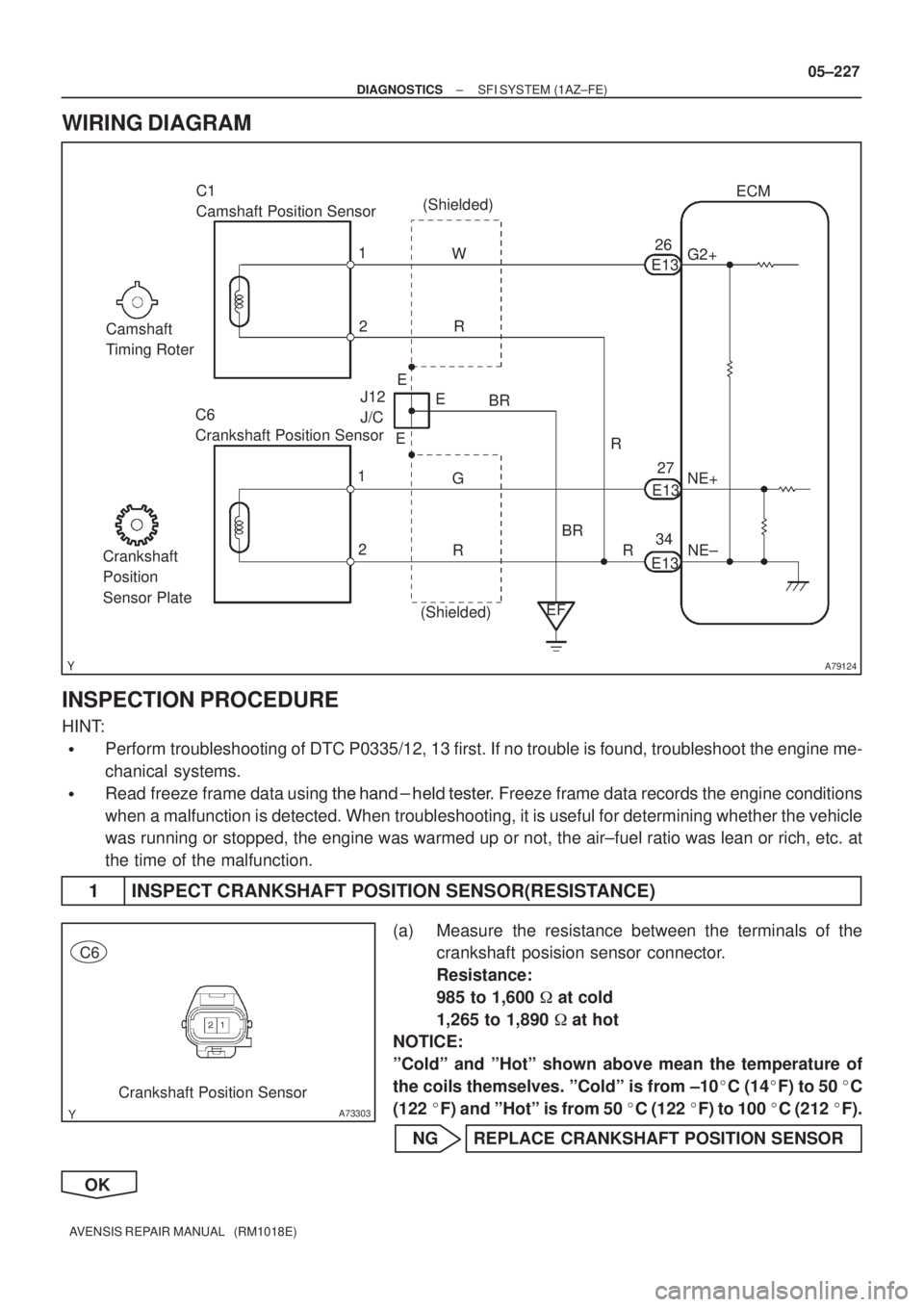
WIRING DIAGRAM
INSPECTION PROCEDURE
HINT:
�Perform troubleshooting of DTC P0335/12, 13 first. If no trouble is found, troubleshoot the engine me-
chanical systems.
�Read freeze frame data using ��� �� ������ �����
� Freeze frame data records the engine conditions
when a malfunction is detected. When troubleshooting, it is useful for determining whether the vehicle
was running or stopped, the engine was warmed up or not, the air±fuel ratio was lean or rich, etc. at
the time of the malfunction.
1 INSPECT CRANKSHAFT POSITION SENSOR(RESISTANCE)
(a) Measure the resistance between the terminals of the
crankshaft posision sensor connector.
Resistance:
985 to 1,600 � at cold
1,265 to 1,890 � at hot
NOTICE:
ºColdº and ºHotº shown above mean the temperature of
the coils themselves. ºColdº is from ±10�C (14�F) to 50 �C
(122 �F) and ºHotº is from 50 �C (122 �F) to 100 �C (212 �F).
NG REPLACE CRANKSHAFT POSITION SENSOR
OK