Page 342 of 5135
A72925
ECM
THW
E2 19
E13
28
E13 BR B±W
1 25V
R E2
Engine Coolant Temperature Sensor
± DIAGNOSTICSSFI SYSTEM (1AZ±FE)
05±199
AVENSIS REPAIR MANUAL (RM1018E)
DTC P0115/22 ENGINE COOLANT TEMPERATURE CIRCUIT
DTC P0117/22 ENGINE COOLANT TEMPERATURE CIRCUIT
LOW INPUT
DTC P0118/22 ENGINE COOLANT TEMPERATURE CIRCUIT
HIGH INPUT
CIRCUIT DESCRIPTION
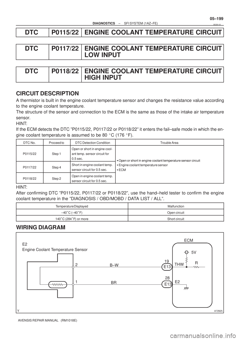
A thermistor is built in the engine coolant temperature sensor and changes the resistance value according
to the engine coolant temperature.
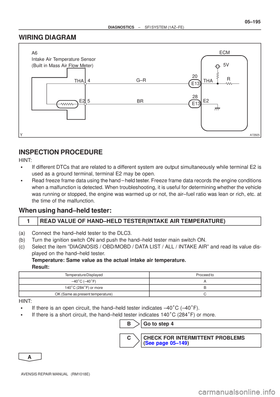
The structure of the sensor and connection to the ECM is the same as those of the intake air temperature
sensor.
HINT:
If the ECM detects the DTC ºP0115/22, P0117/22 or P0118/22º it enters the fail±safe mode in which the en-
gine coolant temperature is assumed to be 80 �C (176 �F).
DTC No.Proceed toDTC Detection ConditionTrouble Area
P0115/22Step 1
Open or short in engine cool-
ant temp. sensor circuit for
0.5 sec.
�Open or short in engine coolant temperature sensor circuit
P0117/22Step 4Short in engine coolant temp.
sensor circuit for 0.5 sec.
�Open or short in engine coolant temperature sensor circuit
�Engine coolant temperature sensor
�ECM
P0118/22Step 2Open in engine coolant temp.
sensor circuit for 0.5 sec.
HINT:
After confirming DTC ºP0115/22, P0117/22 or P0118/22º, use the hand±held tester to confirm the engine
coolant temperature in the ºDIAGNOSIS / OBD/MOBD / DATA LIST / ALLº.
Temperature DisplayedMalfunction
±40 C (±40 F)Open circuit
140 � (284 �� �� ����Short circuit
WIRING DIAGRAM
05C6V±01
Page 348 of 5135
A72925
BR
G±R
28
20
E13 THA
E2 ECM
5 4
A6
Intake Air Temperature Sensor
(Built in Mass Air Flow Meter)
E135V
R
THA
E2
±
DIAGNOSTICS SFI SYSTEM(1AZ±FE)
05±195
AVENSIS REPAIR MANUAL (RM1018E)
WIRING DIAGRAM
INSPECTION PROCEDURE
HINT:
�If different DTCs that are related to a different system are output simultaneously while terminal E2 is
used as a ground terminal, terminal E2 may be open.
�Read freeze frame data using
\b�\b�
��\b� �
�\f
��� Freeze frame data records the engine conditions
when a malfunction is detected. When troubleshooting, it is useful for d\
etermining whether the vehicle
was running or stopped, the engine was warmed up or not, the air±fuel ra\
tio was lean or rich, etc. at
the time of the malfunction.
When using hand±held tester:
1READ VALUE OF HAND±HELD TESTER(INTAKE AIR TEMPERATURE)
(a)Connect the hand±held tester to the DLC3.
(b)Turn the ignition switch ON and push the hand±held tester main switch \
ON.
(c)Select the item ºDIAGNOSIS / OBD/MOBD / DATA LIST / ALL / INTAKE AIRº and read its value dis- played on the hand±held tester.
Temperature: Same value as the actual intake air temperature.
Result:
Temperature DisplayedProceed to
±40�C (±40 ��)A
140 �C (284 ��) or moreB
OK (Same as present temperature)C
HINT:
�If there is an open circuit, the hand±held tester indicates ±40 �C (±40 �F).
�If there is a short circuit, the hand±held tester indicates 140 �C (284 �F) or more.
BGo to step 4
CCHECK FOR INTERMITTENT PROBLEMS (See page 05±149)
A
Page 353 of 5135
A76863
B±Y
Battery FL MAINEngine Room R/B No. 4
G EFI Relay
A6
Mass Air Flow MeterMREL
B±G 4B 1
W±BB±W 53
2
1
32
E128
E9ECM
EFI No. 1
EC 4A 1
Engine Room
J/B No. 4 1A 1
B±G 1 2
EFI 1
Engine Room
R/B No. 1 and
Engine Room
J/B No.14
4
44
4
4
2
1 W±B
B±R
B±RGR
GRIE1 2
EVG 24
E12VG
L±Y 1
3
2 EA112
± DIAGNOSTICSSFI SYSTEM (1AZ±FE)
05±187
AVENSIS REPAIR MANUAL (RM1018E)
WIRING DIAGRAM
INSPECTION PROCEDURE
HINT:
Read freeze frame data using the hand±held tester. Freeze frame data records the engine conditions when
a malfunction is detected. When troubleshooting, it is useful for determining whether the vehicle was running
or stopped, the engine was warmed up or not, the air±fuel ratio was lean or rich, etc. at the time of the mal-
function.
Page 361 of 5135
A75325
HTAF+
+B
AF±
Bank 1, Sensor 1
A7
A/F Sensor
A79112
Bank 2, Sensor 1
A8
A/F Sensor HT
AF+
+B
AF±
B16200
±
DIAGNOSTICS SFI SYSTEM(1AZ±FE)
05±183
AVENSIS REPAIR MANUAL (RM1018E)
WIRING DIAGRAM
Refer to DTC P2237/21 on page 05±248.
INSPECTION PROCEDURE
HINT:
�If different DTCs that are related to a different system are output simultaneously while terminal E2 is
used as a ground terminal, terminal E2 may be open.
�Read freeze frame data using \f�� �� ����\b� \f��\f�
� Freeze frame data records the engine conditions
when a malfunction is detected. When troubleshooting, it is useful for d\
etermining whether the vehicle
was running or stopped, the engine was warmed up or not, the air±fuel ra\
tio was lean or rich, etc. at
the time of the malfunction.
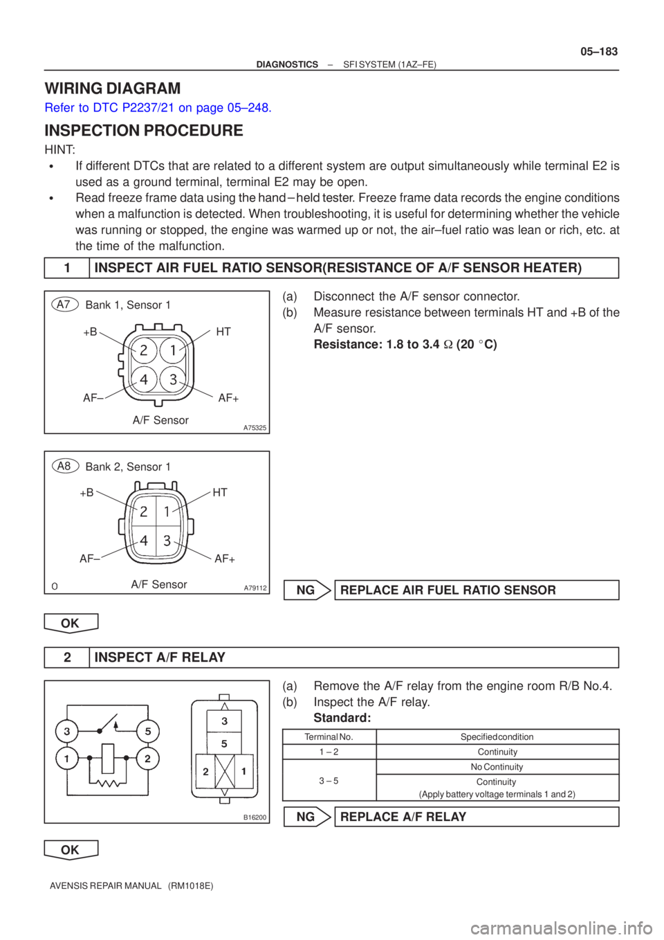
1 INSPECT AIR FUEL RATIO SENSOR(RESISTANCE OF A/F SENSOR HEATER)
(a) Disconnect the A/F sensor connector.
(b) Measure resistance between terminals HT and +B of the A/F sensor.
Resistance: 1.8 to 3.4 � (20 �C)
NG REPLACE AIR FUEL RATIO SENSOR
OK
2 INSPECT A/F RELAY
(a) Remove the A/F relay from the engine room R/B No.4.
(b) Inspect the A/F relay. Standard:
Terminal No.Specified condition
1 ± 2Continuity
No Continuity
3 ± 5Continuity
(Apply battery voltage terminals 1 and 2)
NG REPLACE A/F RELAY
OK
Page 364 of 5135
±
DIAGNOSTICS SFI SYSTEM(1AZ±FE)
05±181
AVENSIS REPAIR MANUAL (RM1018E)
DTCP0016/18CRANKSHAFT POSITION ±CAMSHAFT
POSITION CORRELATION (BANK 1 SENSOR
A)
CIRCUIT DESCRIPTION
Refer to DTC P0335/12, 13 and P0339/13 on page 05±226.
DTC No.DTC Detection ConditionTrouble Area
P0016/18Deviation in crankshaft position sensor signal and VVT sensor
1 signal (2 trip detection logic)�Mechanical system (Timing chain has jumped a tooth, chain
stretched)
� ECM
WIRING DIAGRAM
Refer to DTC P0335/12, 13 and P0339/13 on page 05±226.
INSPECTION PROCEDURE
Read freeze frame data using the hand±held tester. Freeze frame data records the engine conditions when
a malfunction is detected. When troubleshooting, it is useful for determi\
ning whether the vehicle was running
or stopped, the engine was warmed up or not, the air±fuel ratio was lea\
n or rich, etc. at the time of the mal-
function.
1CHECK VALVE TIMING (See page 14±139)
NGADJUST VALVE TIMING (See page 14±139)
OK
CHECK AND REPLACE ECM (See page 01±32)
05C7F±01
Page 366 of 5135
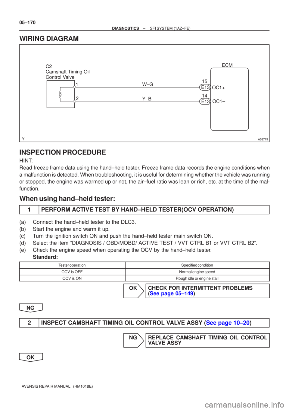
A59779
C2
Camshaft Timing Oil
Control Valve1
2 ECM
W±G OC1+
14
Y±B OC1±
E13
15
E13
05±170
±
DIAGNOSTICS SFI SYSTEM(1AZ±FE)
AVENSIS REPAIR MANUAL (RM1018E)
WIRING DIAGRAM
INSPECTION PROCEDURE
HINT:
Read freeze frame data using the hand±held tester. Freeze frame data records the engine conditions when
a malfunction is detected. When troubleshooting, it is useful for determi\
ning whether the vehicle was running
or stopped, the engine was warmed up or not, the air±fuel ratio was lea\
n or rich, etc. at the time of the mal-
function.
When using hand±held tester:
1PERFORM ACTIVE TEST BY HAND±HELD TESTER(OCV OPERATION)
(a)Connect the hand±held tester to the DLC3.
(b)Start the engine and warm it up.
(c)Turn the ignition switch ON and push the hand±held tester main switch \
ON.
(d)Select the item ºDIAGNOSIS / OBD/MOBD/ ACTIVE TEST / VVT CTRL B1 or V\
VT CTRL B2º.
(e)Check the engine speed when operating the OCV by the hand±held tester. Standard:
Tester operationSpecified condition
OCV is OFFNormal engine speed
OCV is ONRough idle or engine stall
OKCHECK FOR INTERMITTENT PROBLEMS (See page 05±149)
NG
2INSPECT CAMSHAFT TIMING OIL CONTROL VALVE ASSY (See page 10±20)
NG REPLACE CAMSHAFT TIMING OIL CONTROL VALVE ASSY
OK
Page 370 of 5135
A76888
FL MAIN
StarterCircuit
Opening Relay
Start Position SWEFI Relay
AM2
BatteryECM
STA MREL Ignition SWFuel Pump
ST2
ST
Relay
(NE Signal) (A/T)FC
EFISTTr
(M/T)
(A/T) AM2 05±264
± DIAGNOSTICSSFI SYSTEM (1AZ±FE)
AVENSIS REPAIR MANUAL (RM1018E)
FUEL PUMP CONTROL CIRCUIT
CIRCUIT DESCRIPTION
In the diagram below, when the engine is cranked, current flows from terminal ST2 of the ignition switch to
the starter relay coil and also current flows to terminal STA of the ECM (STA signal).
When the STA signal and NE signal are input to the ECM, Tr is turned ON, current flows to the coil of the
E.F.I. circuit opening relay, the relay switches on, power is supplied to the fuel pump and the fuel pump oper-
ates.
While the NE signal is generated (engine running), the ECM keeps Tr ON (circuit opening relay ON) and the
fuel pump also keeps operating.
05C79±01
Page 371 of 5135
A76889
FCECM
IB1 Engine Room
R/B No. 1
Engine Room
J/B No. 1
B±G
FL MAIN
BatteryGR
ECW±B 1AE9 10
32 51
1
3 5
4B 1EFI
EFI
Relay
B±G
F25
Fuel
Pump 4
5
W±B 10 Engine
Room
J/B No. 4 1
24 4
4
4 4A 1C8
Circuit
Opening
Relay B±Y
1
2
1
Engine Room
R/B No. 4
BR B±WB±WB±WB±W
L±BG±Y G±Y GR
B±YGR
MREL E98
IE12
6
IC3
± DIAGNOSTICSSFI SYSTEM (1AZ±FE)
05±265
AVENSIS REPAIR MANUAL (RM1018E)
WIRING DIAGRAM