Page 3688 of 5135

D25674
D09176
D03900
D03900
C83144
40±66
± AUTOMATIC TRANSMISSION / TRANSAUTOMATIC TRANSAXLE ASSY (U241E)
U241E A/T REPAIR MANUAL (RM840U)
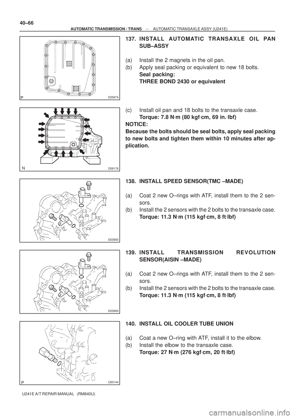
137. I N S TA L L A U TO M AT I C TRANSAXLE OIL PAN
SUB±ASSY
(a) Install the 2 magnets in the oil pan.
(b) Apply seal packing or equivalent to new 18 bolts.
Seal packing:
THREE BOND 2430 or equivalent
(c) Install oil pan and 18 bolts to the transaxle case.
Torque: 7.8 N�m (80 kgf�cm, 69 in.�lbf)
NOTICE:
Because the bolts should be seal bolts, apply seal packing
to new bolts and tighten them within 10 minutes after ap-
plication.
138. INSTALL SPEED SENSOR(TMC ±MADE)
(a) Coat 2 new O±rings with ATF, install them to the 2 sen-
sors.
(b) Install the 2 sensors with the 2 bolts to the transaxle case.
Torque: 11.3 N�m (115 kgf�cm, 8 ft�lbf)
139. I N S TA L L TRANSMISSION REVOLUTION
SENSOR(AISIN ±MADE)
(a) Coat 2 new O±rings with ATF, install them to the 2 sen-
sors.
(b) Install the 2 sensors with the 2 bolts to the transaxle case.
Torque: 11.3 N�m (115 kgf�cm, 8 ft�lbf)
140. INSTALL OIL COOLER TUBE UNION
(a) Coat a new O±ring with ATF, install it to the elbow.
(b) Install the elbow to the transaxle case.
Torque: 27 N�m (276 kgf�cm, 20 ft�lbf)
Page 3689 of 5135
C83143
C83142
D08034
D08093
± AUTOMATIC TRANSMISSION / TRANSAUTOMATIC TRANSAXLE ASSY (U241E)
40±67
U241E A/T REPAIR MANUAL (RM840U)
141. INSTALL OIL COOLER TUBE UNION
(a) Coat a new O±ring with ATF, install it to the union.
(b) Install the union to the transaxle case.
Torque: 27 N�m (280 kgf�cm, 20 ft�lbf)
142. INSTALL TRANSAXLE CASE NO.1 PLUG
(a) Coat 4 new O±rings with ATF, install them to the 4 trans-
axle case No. 1 plugs.
(b) Install the 4 transaxle case No. 1 plugs to the transaxle
case.
Torque: 7.4 N�m (75 kgf�cm, 65 in.�lbf)
143. INSTALL BREATHER PLUG HOSE
(a) Install the breather plug hose to the breather No. 2 plug.
144. INSTALL PARK/NEUTRAL POSITION SWITCH ASSY
(a) Install the park/neutral position switch onto the manual
valve lever shaft and temporarily install the 2 adjusting
bolts.
(b) Install a new nut stopper and nut.
Torque: 6.9 N�m (70 kgf�cm, 61 in.�lbf)
(c) Temporarily install control shaft lever.
Page 3690 of 5135
D08094
D09642
D08033
D08032
40±68
± AUTOMATIC TRANSMISSION / TRANSAUTOMATIC TRANSAXLE ASSY (U241E)
U241E A/T REPAIR MANUAL (RM840U)
(d) Turn the lever counterclockwise until it stops, and then
turn it clockwise 2 notches.
(e) Remove the control shaft lever.
(f) Align the groove with neutral basic line.
(g) Tighten the 2 bolts.
Torque: 5.4 N�m (55 kgf�cm, 48 in.�lbf)
(h) Using a screwdriver, stake the nut with the nut stopper.
(i) Install the control shaft lever, washer and nut.
Torque: 13 N�m (133 kgf�cm, 10 ft�lbf)
145. INSTALL SPEEDOMETER DRIVEN HOLE (ATM) COVER SUB±ASSY
(a) Coat the new O±ring with ATF and install it to the speedometer driven hole cover.
(b) Install the bolt and speedometer driven hole cover sub±assy to the transaxle assy.
Torque: 7.0 N�m (70 kgf�cm, 61 in.�lbf)
Page 3701 of 5135
4006W±01
C83132
Match±marks
C83133
C83134
D25211
SST
40±100
± AUTOMATIC TRANSMISSION / TRANSFRONT DIFFERENTIAL ASSY (U241E)
U241E A/T REPAIR MANUAL (RM840U)
FRONT DIFFERENTIAL ASSY (U241E)
OVERHAUL
1. REMOVE FRONT DIFFERENTIAL RING GEAR
(a) Place the match±marks on the ring gear and differential
case.
(b) Remove the 10 bolts.
(c) Using a plastic hammer, tap on the ring gear to remove it
from the case.
2. REMOVE FR DIFFERENTIAL CASE FRONT TAPERED
ROLLER BEARING
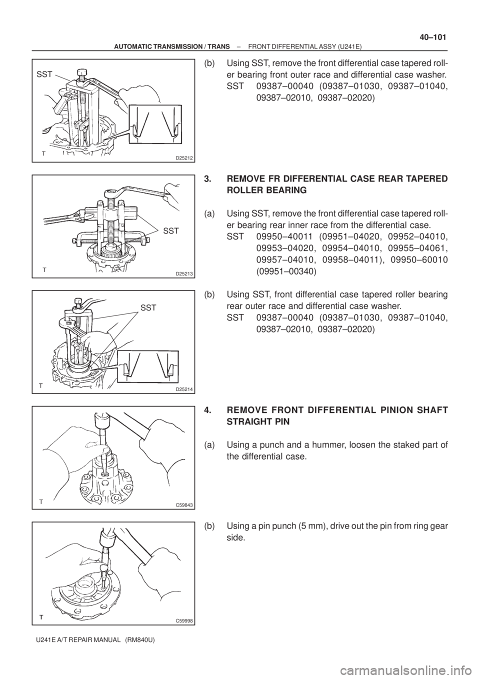
(a) Using SST, remove the front differential case tapered roll-
er bearing front inner race from the differential case.
SST 09950±40011 (09951±04020, 09952±04010,
09953±04020, 09954±04010, 09955±04061,
09957±04010, 09958±04011), 09950±60010
(09951±00340)
Page 3702 of 5135

D25212
SST
D25213
SST
D25214
SST
C59843
C59998
± AUTOMATIC TRANSMISSION / TRANSFRONT DIFFERENTIAL ASSY (U241E)
40±101
U241E A/T REPAIR MANUAL (RM840U)
(b) Using SST, remove the front differential case tapered roll-
er bearing front outer race and differential case washer.
SST 09387±00040 (09387±01030, 09387±01040,
09387±02010, 09387±02020)
3. REMOVE FR DIFFERENTIAL CASE REAR TAPERED
ROLLER BEARING
(a) Using SST, remove the front differential case tapered roll-
er bearing rear inner race from the differential case.
SST 09950±40011 (09951±04020, 09952±04010,
09953±04020, 09954±04010, 09955±04061,
09957±04010, 09958±04011), 09950±60010
(09951±00340)
(b) Using SST, front differential case tapered roller bearing
rear outer race and differential case washer.
SST 09387±00040 (09387±01030, 09387±01040,
09387±02010, 09387±02020)
4. REMOVE FRONT DIFFERENTIAL PINION SHAFT
STRAIGHT PIN
(a) Using a punch and a hummer, loosen the staked part of
the differential case.
(b) Using a pin punch (5 mm), drive out the pin from ring gear
side.
Page 3703 of 5135
C83135
C83136
D25600
SST
D25599
SST
C83137
40±102
± AUTOMATIC TRANSMISSION / TRANSFRONT DIFFERENTIAL ASSY (U241E)
U241E A/T REPAIR MANUAL (RM840U)
5. REMOVE FRONT DIFFERENTIAL PINION SHAFT
NO.1
(a) Remove the front differential pinion shaft No. 1 from the
differential case.
6. REMOVE FRONT DIFFERENTIAL SIDE GEAR
(a) Remove the 2 front differential pinions, 2 pinion thrust
washers, 2 front differential side gears and 2 side gear
thrust washers from the differential case.
7. REMOVE DIFFERENTIAL SIDE BEARING RETAINER
OIL SEAL
(a) Place the transaxle case in vise.
(b) Using SST, remove the oil seal.
SST 09308±00010
8. REMOVE TRANSAXLE HOUSING OIL SEAL
(a) Place the transaxle housing in vise.
(b) Using SST, remove the oil seal.
SST 09308±00010
9. INSTALL FRONT DIFFERENTIAL SIDE GEAR
(a) Coat the 2 front differential side gears, 2 side gear thrust
washers, 2 front differential pinions and 2 pinion thrust
washers with ATF and install them to the differential case.
Page 3704 of 5135
C83135
C83138
C60005
C60006
± AUTOMATIC TRANSMISSION / TRANSFRONT DIFFERENTIAL ASSY (U241E)
40±103
U241E A/T REPAIR MANUAL (RM840U)
10. INSTALL FRONT DIFFERENTIAL PINION SHAFT NO.1
(a) Coat the front differential pinion shaft No. 1 with ATF and
install it to the differential case.
11. INSPECT FRONT DIFFERENTIAL SIDE GEAR
BACKLASH
(a) Using a dial indicator, inspect the backlash of the side
gear.
Standard backlash:
0.05 ± 0.20 mm (0.0020 ± 0.0079 in.)
Thrust washer thickness:
MarkThickness
±1.0 mm (0.0394 in.)
±1.1 mm (0.0433in.)
±1.2 mm (0.0472 in.)
±1.3 mm (0.0512 in.)
12. INSTALL FRONT DIFFERENTIAL PINION SHAFT
STRAIGHT PIN
(a) Using a pin punch and hammer, install the pinion shaft
straight pin.
(b) Using a chisel and hammer, stake the differential case.
Page 3705 of 5135

D25218
SST
D25219
SST
D25216
SST
D25217
SST
D25215
90 ± 100 �C (194 ± 230 �F) 40±104
± AUTOMATIC TRANSMISSION / TRANSFRONT DIFFERENTIAL ASSY (U241E)
U241E A/T REPAIR MANUAL (RM840U)
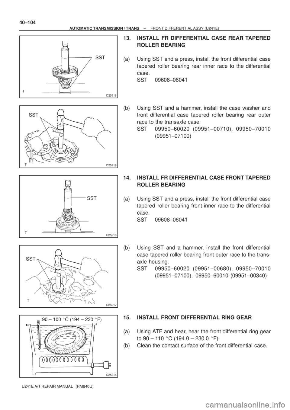
13. INSTALL FR DIFFERENTIAL CASE REAR TAPERED
ROLLER BEARING
(a) Using SST and a press, install the front differential case
tapered roller bearing rear inner race to the differential
case.
SST 09608±06041
(b) Using SST and a hammer, install the case washer and
front differential case tapered roller bearing rear outer
race to the transaxle case.
SST 09950±60020 (09951±00710), 09950±70010
(09951±07100)
14. INSTALL FR DIFFERENTIAL CASE FRONT TAPERED
ROLLER BEARING
(a) Using SST and a press, install the front differential case
tapered roller bearing front inner race to the differential
case.
SST 09608±06041
(b) Using SST and a hammer, install the front differential
case tapered roller bearing front outer race to the trans-
axle housing.
SST 09950±60020 (09951±00680), 09950±70010
(09951±07100), 09950±60010 (09951±00340)
15. INSTALL FRONT DIFFERENTIAL RING GEAR
(a) Using ATF and hear, hear the front differential ring gear
to 90 ± 110 �C (194.0 ± 230.0 �F).
(b) Clean the contact surface of the front differential case.