Page 1480 of 5135
I35615
Battery FL MAIN
B±G (*1)B±G (*1)
4B 4A 4D
1 11
12 ALT
B±G (*1) B±G (*1)
Engine Room R/B No.4, Engine Room J/B No.4 1A1 DCC
1 Engine Room R/B No.1, Engine Room J/B No.1 B (*2) B (*2)
33
3 ALT
12W (*2)
ED11 B±L (*2)
B±W
IP1 IE454
(*6) (*3)B±W
6 6
1 2 RAD No.2Fuse Block
Engine Room R/B No.3 L±Y (*3)
L±Y (*4)
L±Y (*5)
INBR (*3)
W±B (*6)R9GND 7 DNDB DH
DH1 134
AM1 RAD No.1 Driver Side J/B
G±R I12 Ignition Switch
AM1 ACC
3 2GGR
J8 J8J20 J20 FF FF J/C
GR
R9 R9
ACC CE CB4
8 Center J/B
L±Y (*3) L±Y (*4) L±Y (*5)L±Y (*5) J24
J/C
EE
4
3+B Radio Receiver Assy
*1: Gasoline
*2: 1CD±FTV
*3: LHD*4: RHD, 1CD±FTV, w/o Multi±display
*5: RHD, Except *4
*6: RHD(*3) (*3)(*6) (*6)
1
2
± DIAGNOSTICSAUDIO SYSTEM
05±1413
AVENSIS REPAIR MANUAL (RM1018E)
POWER SOURCE CIRCUIT (RADIO RECEIVER ASSY)
WIRING DIAGRAM
05C4Z±01
Page 1481 of 5135
I35616
GND
ACC
+B
05±1414
±
DIAGNOSTICS AUDIO SYSTEM
AVENSIS REPAIR MANUAL (RM1018E)
INSPECTION PROCEDURE
1INSPECT RADIO RECEIVER ASSY(BU, ACC, GND)
(a)Remove the radio receiver assy.
(b)Check continuity between terminals at each condition, as shown in the chart.
Standard:
Tester connectionConditionSpecified condition
GND ± Body groundAlwaysContinuity
(c)Check the voltage between terminals at each condition,
as shown in the chart.
Standard:
Tester connectionConditionSpecified condition
+B ± GNDAlways10 to 14 V
ACC ± GNDIgnition SW ACC10 to 14 V
NGREPAIR OR REPLACE HARNESS OR CONNECTOR (See page 01±32)
OK
2 CHECK FOR PROBLEM SYMPTOMS TABLE
(a)Check problem symptoms table (See page 05±1412).
Suspected areas are clearedA
Suspected areas still existB
B PROCEED TO NEXT CIRCUIT INSPECTION SHOWN ON PROBLEM SYMPTOMS TABLE (See
page 05±1412 )
A
REPLACE RADIO RECEIVER ASSY
Page 1482 of 5135
0549M±11
05±1412
±
DIAGNOSTICS AUDIO SYSTEM
AVENSIS REPAIR MANUAL (RM1018E)
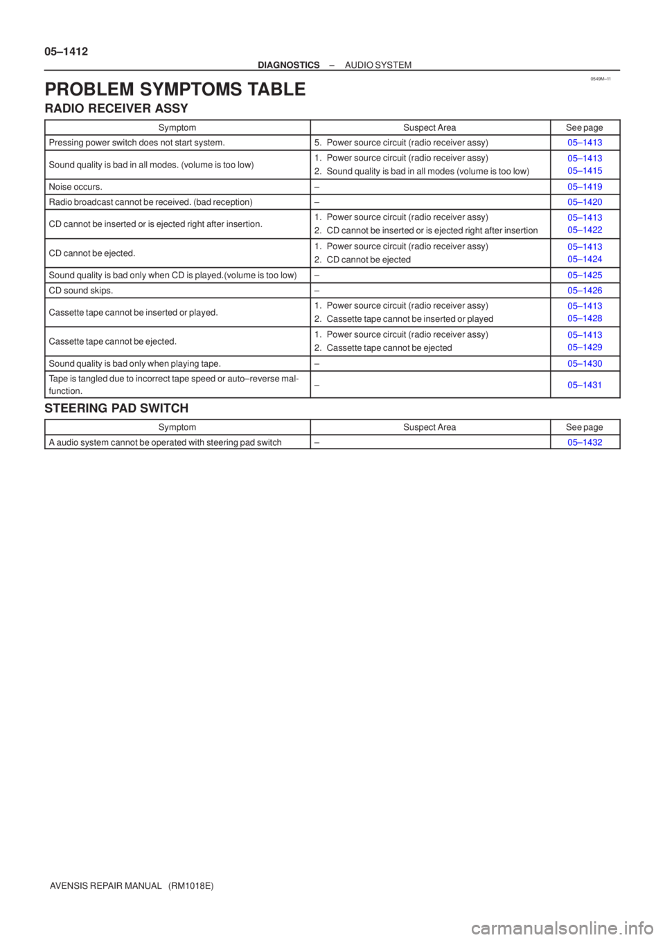
PROBLEM SYMPTOMS TABLE
RADIO RECEIVER ASSY
SymptomSuspect AreaSee page
Pressing power switch does not start system.5. Power source circuit (radio receiver assy)05±1413
Sound quality is bad in all modes. (volume is too low)1. Power source circuit (radio receiver assy)
2. Sound quality is bad in all modes (volume is too low)05±1413
05±1415
Noise occurs.±05±1419
Radio broadcast cannot be received. (bad reception)±05±1420
CD cannot be inserted or is ejected right after insertion.1. Power source circuit (radio receiver assy)
2. CD cannot be inserted or is ejected right after insertion05±1413
05±1422
CD cannot be ejected.1. Power source circuit (radio receiver assy)
2. CD cannot be ejected05±1413
05±1424
Sound quality is bad only when CD is played.(volume is too low)±05±1425
CD sound skips.±05±1426
Cassette tape cannot be inserted or played.1. Power source circuit (radio receiver assy)
2. Cassette tape cannot be inserted or played05±1413
05±1428
Cassette tape cannot be ejected.1. Power source circuit (radio receiver assy)
2. Cassette tape cannot be ejected05±1413
05±1429
Sound quality is bad only when playing tape.±05±1430
Tape is tangled due to incorrect tape speed or auto±reverse mal-
function.±05±1431
STEERING PAD SWITCH
SymptomSuspect AreaSee page
A audio system cannot be operated with steering pad switch±05±1432
Page 1483 of 5135
05C4Y±01
I35611
R10 R12 R11 R9
05±1410
± DIAGNOSTICSAUDIO SYSTEM
AVENSIS REPAIR MANUAL (RM1018E)
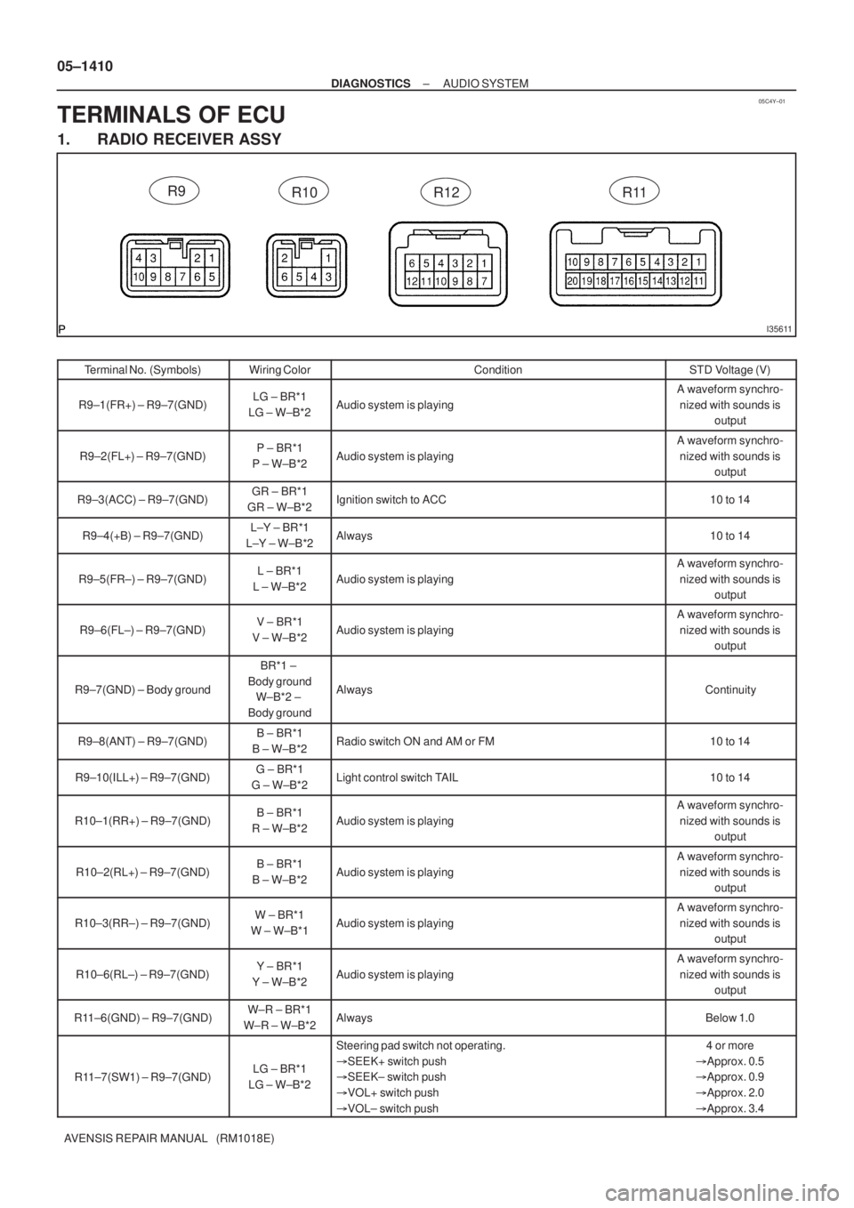
TERMINALS OF ECU
1. RADIO RECEIVER ASSY
Terminal No. (Symbols)Wiring ColorConditionSTD Voltage (V)
R9±1(FR+) ± R9±7(GND)LG ± BR*1
LG ± W±B*2Audio system is playing
A waveform synchro-
nized with sounds is
output
R9±2(FL+) ± R9±7(GND)P ± BR*1
P ± W±B*2Audio system is playing
A waveform synchro-
nized with sounds is
output
R9±3(ACC) ± R9±7(GND)GR ± BR*1
GR ± W±B*2Ignition switch to ACC10 to 14
R9±4(+B) ± R9±7(GND)L±Y ± BR*1
L±Y ± W±B*2Always10 to 14
R9±5(FR±) ± R9±7(GND)L ± BR*1
L ± W±B*2Audio system is playing
A waveform synchro-
nized with sounds is
output
R9±6(FL±) ± R9±7(GND)V ± BR*1
V ± W±B*2Audio system is playing
A waveform synchro-
nized with sounds is
output
R9±7(GND) ± Body ground
BR*1 ±
Body ground
W±B*2 ±
Body ground
AlwaysContinuity
R9±8(ANT) ± R9±7(GND)B ± BR*1
B ± W±B*2Radio switch ON and AM or FM10 to 14
R9±10(ILL+) ± R9±7(GND)G ± BR*1
G ± W±B*2Light control switch TAIL10 to 14
R10±1(RR+) ± R9±7(GND)B ± BR*1
R ± W±B*2Audio system is playing
A waveform synchro-
nized with sounds is
output
R10±2(RL+) ± R9±7(GND)B ± BR*1
B ± W±B*2Audio system is playing
A waveform synchro-
nized with sounds is
output
R10±3(RR±) ± R9±7(GND)W ± BR*1
W ± W±B*1Audio system is playing
A waveform synchro-
nized with sounds is
output
R10±6(RL±) ± R9±7(GND)Y ± BR*1
Y ± W±B*2Audio system is playing
A waveform synchro-
nized with sounds is
output
R11±6(GND) ± R9±7(GND)W±R ± BR*1
W±R ± W±B*2AlwaysBelow 1.0
R11±7(SW1) ± R9±7(GND)LG ± BR*1
LG ± W±B*2
Steering pad switch not operating.
�SEEK+ switch push
�SEEK± switch push
�VOL+ switch push
�VOL± switch push4 or more
�Approx. 0.5
�Approx. 0.9
�Approx. 2.0
�Approx. 3.4
Page 1489 of 5135
I34725
Multi±display
(CRT Display) Display
CTX±
CTX+
TX3+
TX3±
GTX+
GTX±M2
M1 M2
M1
M1
M110
5
12
24
5
18LG
V
G±Y
G
P
LG10
5Navigation ECU
Body ECU
(Combination Meter Assy)
Radio Receiver Assy3
4
9
10 C10
C10
R6
R6N4
N4TX±
TX+
TX± TX+
± DIAGNOSTICSNAVIGATION SYSTEM
05±1471
AVENSIS REPAIR MANUAL (RM1018E)
AVC±LAN CIRCUIT
WIRING DIAGRAM
INSPECTION PROCEDURE
1 INSPECT APPARATUS
(a) Choose the apparatus to be inspected.
ApparatusGo to step
Radio receiver assyA
Navigation ECUB
Body ECU (Combination Meter Assy)C
B Go to step 4
C Go to step 6
A
05C3K±01
Page 1490 of 5135
I35665
GTX+GTX±
TX+
TX±
Radio Receiver Assy: Multi±display (CRT Display) Display:
M2
R12
05±1472
±
DIAGNOSTICS NAVIGATION SYSTEM
AVENSIS REPAIR MANUAL (RM1018E)
2SERVICE CHECK MODE(RADIO RECEIVER ASSY)
(a)Perform the service check. (1)Start the diagnosis system and read the check result for the radio recei\
ver assy.
Standard:
AºNCONº is displayed or nothing is displayed (AUDIO H/U)
BºGOODº is displayed
BREPLACE MULTI±DISPLAY (CRT DISPLAY) DISPLAY (See page 67±6)
A
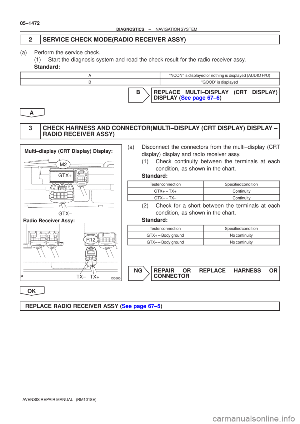
3CHECK HARNESS AND CONNECTOR(MULTI±DISPLAY (CRT DISPLAY) DISPLAY ± RADIO RECEIVER ASSY)
(a)Disconnect the connectors from the multi±display (CRT
display) display and radio receiver assy.
(1)Check continuity between the terminals at eachcondition, as shown in the chart.
Standard:
Tester connectionSpecified condition
GTX+ ± TX+Continuity
GTX± ± TX±Continuity
(2)Check for a short between the terminals at each condition, as shown in the chart.
Standard:
Tester connectionSpecified condition
GTX+ ± Body groundNo continuity
GTX± ± Body groundNo continuity
NGREPAIR OR REPLACE HARNESS OR CONNECTOR
OK
REPLACE RADIO RECEIVER ASSY (See page 67±5)
Page 1503 of 5135
05C3F±01
I34714
Driver Side J/B
� RAD No.1 Fuse
� AM1 Fuse
� GAUGE1 Fuse
� IG1 RelayFront No.1
Speaker AssyMulti±display
(CRT display)
Display
Steering Pad
Switch LH Engine Room R/B No.1 and
Engine Room J/B No.1
� DCC Fuse
� AM2 Fuse
Front No.2
Speaker Assy
Steering Pad
Switch RH Sub R/B (LHD)
Sub R/B (RHD)
Navigation
Antenna AssyTelephone Microphone AssyRadio Receiver Assy
Navigation Controller Assy Navigation Controller Holder Navigation ECU Combination
Meter Assy
(Body ECU)
Body ECU
(Combination Meter Assy)
05±1460
± DIAGNOSTICSNAVIGATION SYSTEM
AVENSIS REPAIR MANUAL (RM1018E)
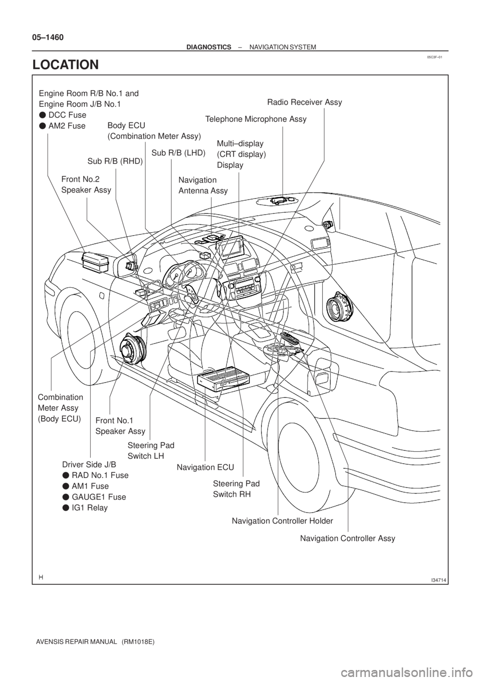
LOCATION
Page 1504 of 5135

05C3E±01
± DIAGNOSTICSNAVIGATION SYSTEM
05±1453
AVENSIS REPAIR MANUAL (RM1018E)
DIAGNOSTIC TROUBLE CODE CHART
TermsMeaning
Physical addressThree±digit code (shown in hexadecimal) which is given to each component com-
prising the AVC±LAN.
Corresponding to the function, individual symbols are specified.
Logical addressTwo±digit code (shown in hexadecimal) which is given to each function comprising
the inner system of the AVC±LAN.
1. RADIO RECEIVER ASSY (Physical address: 190)
HINT:
�*1: Even if no failure is detected, this code may be stored depending on the battery condition or voltage
for starting an engine.
�*2: This code is stored in 180 sec. after the power supply connector is pulled out after engine start.
�*3: This code may be stored when the ignition switch is turned again after engine start.
�*4: This code may be stored when the ignition switch is turned again in 1 min. after engine start.
(a) Logical address: 01 (Communication control)
DTCDiagnosis itemConditionCountermeasure and inspected parts
D5
*1Registered component disconnectedComponent shown by sub±code is or was
disconnected from system with ignition
switch ACC or ON.
Communication with component shown by
sub±code is not ensured when engine is
started.�Check harness for power supply of compo-
nent shown by sub±code.
�Check harness for communication system
of component shown by sub±code.
D6
*1Absence of MasterComponent in which this code is recorded
has been disconnected from system with
ignition switch ACC or ON. Or, when this
code was recorded, multi±display (CRT dis-
play) display was disconnected.�Check harness for power supply system of
multi±display (CRT display) display.
�Check harness for communication system
of multi±display (CRT display) display.
D8
*2No response to connection checkComponent shown by sub±code is or was
disconnected from system after engine is
started.�Check harness for power supply of compo-
nent shown by sub±code.
�Check harness for communication system
of component shown by sub±code.
D9
*1Last Mode ErrorComponent operated (sound and/or image
was provided) before engine stop is or was
disconnected with ignition switch ACC or
ON.�Check harness for power supply of compo-
nent shown by sub±code.
�Check harness for communication system
of component shown by sub±code.
DANo Response to ON/OFF InstructionNo response is identified when changing
mode (audio and visual mode change).
Detected when sound and picture does not
change by button operation�Check harness for power supply system of
component shown by sub±code.
�Check harness for communication system
of component shown by sub±code.
�If error occurs again, replace component
shown by auxiliary code
DB
*1Mode Status ErrorDual alarm is detected.�Check harness for power supply system of
component shown by sub±code.
�Check harness for communication system
of component shown by sub±code.
DC
*4Transmission ErrorTransmission to component shown by sub±
code has been failed.
(This code does not necessarily mean actu-
al failure.)If same sub±code is recorded in other com-
ponent(s), check harness for power supply
and communication system of all compo-
nents shown by code.
DD
*4Master Reset (Momentary Interruption)After engine is started, multi±display (CRT
display) display was disconnected from sys-
tem.�Check harness for power supply system of
multi±display (CRT display) display.
�Check harness for communication system
of multi±display (CRT display) display.
�If this error occurs frequently, replace mul-
ti±display (CRT display) display.