Page 1539 of 5135
I35657
S15
Steering Pad Switch LH
Multi±display
(CRT Display) DisplayAU1
AU2
EAU12
11
10LG (*1)
P (*1)
W±R (*1)
GTX+
GTX±
CTX±
CTX+M1
M1
M2
M25
18
10
5P
LG
LG
V
T11
Telephone Microphone Assy
MACC
MIC+
MIC±5
4
2R
B
W
(Shielded)17
ID1
ID1
ID1
ID118
16
14R
B
W
(Shielded)Radio Receiver Assy
7
8
6 R7
R7
R7SW1
SW2
GND
TX+
TX± R6
R69
10
Navigation ECU
TX±
TX+
MACC
MIC+
MIC±
SGND N4
N4
N5
N5
N5
N54
3
5
6 BR
BR
*1: w/ Steering SW10
5 05±1494
± DIAGNOSTICSNAVIGATION SYSTEM
AVENSIS REPAIR MANUAL (RM1018E)
THE SYSTEM CANNOT BE OPERATED BY THE VOICE SOUND
WIRING DIAGRAM
05C3W±01
Page 1548 of 5135
±
DIAGNOSTICS NAVIGATION SYSTEM
05±1487
AVENSIS REPAIR MANUAL (RM1018E)
GPS MARK DOES NOT APPEAR
INSPECTION PROCEDURE
1CHECK MARK DISPLAY
(a)Check that the malfunction disappears when placing the vehicle outdoors with \
a good view.
Standard: GPS mark is displayed.
HINT:
At the place surrounded by the architecture, the vehicle cannot receive \
the GPS radio wave.
OKSYSTEM OK
NG
2CHECK OPTIONAL COMPONENT
(a)Check for optional component. (1)Check if there are any optional components on the vehicle.
Standard: There are no optional components on the vehicle.
(2)Check if there is anything such as film stuck to the window or any metal obje\
cts on the instrument
panel.
Standard: There is nothing such as film stuck to the window or any metal objects on the instru-
ment panel.
NGEFFECT FROM OPTIONAL COMPONENT
OK
3REPLACE NAVIGATION ANTENNA ASSY (See page 67±28)
Standard: Normally returns. NG REPLACE NAVIGATION ECU (See page 67±27)
OK
SYSTEM OK
05C3R±01
Page 1549 of 5135

VEHICLE POSITION IS DEVIATED FROM CORRECT POINT BADLY
INSPECTION PROCEDURE
1CHECK DISPLAY(GPS MARK DISPLAY)
(a)Preparation f")
±
DIAGNOSTICS NAVIGATION SYSTEM
05±1485
AVENSIS REPAIR MANUAL (RM1018E)
VEHICLE POSITION IS DEVIATED FROM CORRECT POINT BADLY
INSPECTION PROCEDURE
1CHECK DISPLAY(GPS MARK DISPLAY)
(a)Preparation for the pre±check.
(1)Place the vehicle outdoors with a good view of the GPS mark.
(b)Check the screen display. (1)Turn the ignition switch ON.
(2)Turn the power switch of the radio receiver assy ON to display the map.
Standard: ''GPS'' mark appears
NGPROCEED TO NEXT CIRCUIT INSPECTIONSHOWN ON PROBLEM SYMPTOMS TABLE
(See page 05±1464)
OK
2 CHECK WHEN THIS HAPPENS
(a) Check the abnormal condition. (1) Check the point in which the trouble occurs.
Standard:
AThe trouble occurs outside the specific area
BThe trouble occurs in the specific area
HINT:
At the place difficult to specify the vehicle position (a by±pass road, a overhand r\
oad, a loop road, or several±
storied car park, etc.), the vehicle position may be out of the point due to t\
he wrong matching.
B SYSTEM OK
A
3 CHECK DISPLAY(AUTOMATIC CALIBRATION)
(a) Check the screen display. (1) Check the color of ''Automatic calibration'' switch at the distance correction screen.
Standard: Green (''Automatic calibration'' switch)
OK SYSTEM OK
NG
05C3Q±01
Page 1553 of 5135
I34726
Radio Receiver Assy
FL±
FL+
FR±
FR+6
12
5 R4
R4
R4
R4LG (*1)
R (*1)
R (*2)
W (*2)Navigation ECU
10
N3
N31AUI±
AUI+
11
N3
N32AUO±
AUO+ F21
Front No.1
Speaker Assy LH
F22
Front No.1
Speaker Assy RH2
1
LG1 LT16
Tweeter Front LH
(±) IN
(+) OUT(+) IN (±) OUT
2
34V
P6
IA1
IA1
IL1
IL1V (*1)
P (*1)
2
1
P1 VT17
Tweeter Front RH
(±) IN
(+) OUT(+) IN (±) OUT
2
34LGL61
1
LG (*2) L (*2)
*1: LHD
*2: RHD
± DIAGNOSTICSNAVIGATION SYSTEM
05±1479
AVENSIS REPAIR MANUAL (RM1018E)
FRONT SPEAKER (DRIVER SIDE) ONLY IS NOT HEARD
WIRING DIAGRAM
05C3N±01
Page 1554 of 5135

INSPECTION PROCEDURE
1 CHECK SETTING(THE VOLUME")
I35667
AUI+
AUI±
FL± FL+
FR±FR+
Navigation ECU:
Radio Receiver Assy:
N3
R4
05±1480
± DIAGNOSTICSNAVIGATION SYSTEM
AVENSIS REPAIR MANUAL (RM1018E)
INSPECTION PROCEDURE
1 CHECK SETTING(THE VOLUME OF THE NAVIGATION VOICE SOUND)
(a) Check the settings.
(1) Set the volume MAX at the voice sound settings on the menu.
Standard: ºThis system will guide you in this volumeº is produced.
OK Go to step 4
NG
2 CHECK HARNESS AND CONNECTOR(NAVIGATION ECU ± RADIO RECEIVER
ASSY)
(a) Disconnect the connector between the navigation ECU
and radio receiver assy.
(1) Check continuity between the terminals at each
condition, as shown in the chart.
Standard:
Tester connectionSpecified condition
FL+*1, FR+*2 ± AUI+Continuity
FL±*1, FR±*2 ± AUI±Continuity
*1: LHD Models
*2: RHD Models
(2) Check for a short between the terminals at each
condition, as shown in the chart.
Standard:
Tester connectionSpecified condition
AUI+ ± Body groundNo continuity
AUI± ± Body groundNo continuity
NG REPAIR OR REPLACE HARNESS OR
CONNECTOR
OK
Page 1555 of 5135
I35668
FL+FR+
FR±FL±
R4
±
DIAGNOSTICS NAVIGATION SYSTEM
05±1481
AVENSIS REPAIR MANUAL (RM1018E)
3INSPECT RADIO RECEIVER ASSY(FL+(*1), FL±(*1), FR+(*2), FR±(*2), \
GND)
(a)Remove the radio receiver assy.
(b)Using an oscilloscope, check the signal waveform be-
tween the terminals FL+*
1, FL±*1, FR+*2, FR±*2 and GND
of stereo component amplifier assy.
*1: LHD Models
*2: RHD Models
Standard:
Tester connectionConditionSpecified condition
FL+*1, FR+*2 ± GNDWhile voice sound is being producedA waveform synchronized with sound is output
FL±*1, FL±*2 ±GNDWhile voice sound is being producedA waveform synchronized with sound is output
NGREPLACE RADIO RECEIVER ASSY (See page 67±5)
OK
4 INSPECT FRONT NO.1 SPEAKER ASSY
(a) Resistance check (1) Check resistance between the terminals of the front No.1 speaker assy.
Standard: 4 �
NOTICE:
The speaker should not be removed for checking
NG REPLACE FRONT NO.1 SPEAKER ASSY (See page 67±10)
OK
Page 2053 of 5135
A76722
A76723
A64033
A64034
A64034
± ENGINE MECHANICALPARTIAL ENGINE ASSY (1ZZ±FE/3ZZ±FE)
14±37
AVENSIS REPAIR MANUAL (RM1018E)
85. REMOVE EXHAUST MANIFOLD HEAT INSULATOR
NO.1
(a) Disconnect the heated oxygen sensor connector.
(b) Remove the 3 bolts and the nut, and then remove the ex-
haust manifold heat insulator.
86. REMOVE EXHAUST MANIFOLD
(a) Remove the 5 nuts, then remove the exhaust manifold
and the gasket.
87. REMOVE ENGINE COOLANT TEMPERATURE
SENSOR
(a) Using SST, remove the engine coolant temperature sen-
sor.
SST 09817±33190
88. REMOVE RADIO SETTING CONDENSER
(a) Remove the bolt and the condenser.
89. REMOVE WATER BY±PASS HOSE NO.2
90. REMOVE RADIATOR HOSE INLET
91. REMOVE HEATER INLET WATER HOSE
92. REPLACE PARTIAL ENGINE ASSY
93. INSTALL RADIO SETTING CONDENSER
(a) Install the condenser with the bolt.
Torque: 10 N�m (102 kgf�cm, 7 ft�lbf)
Page 2068 of 5135
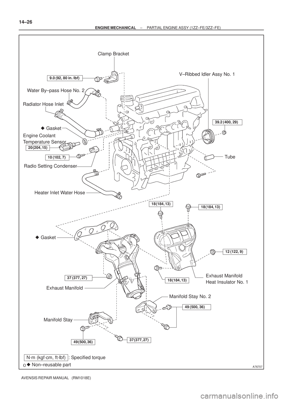
A76707
Water By±pass Hose No. 2
Radiator Hose Inlet
Heater Inlet Water Hose
� Gasket
Exhaust Manifold
Manifold StayExhaust Manifold
Heat Insulator No. 1
� Gasket
Engine Coolant
Temperature Sensor
� Non±reusable part
N´m (kgf´cm, ft´lbf) : Specified torque
20 (204, 15)
9.0 (92, 80 in.�lbf)
37 (377, 27)
18 (184, 13)
49 (500, 36)
Clamp Bracket
10 (102, 7)
Radio Setting Condenser
V±Ribbed Idler Assy No. 1
Tube
18 (184, 13)
12 (122, 9)
Manifold Stay No. 2
49 (500, 36)
37 (377, 27)18 (184, 13)
39.2 (400, 29)
14±26
± ENGINE MECHANICALPARTIAL ENGINE ASSY (1ZZ±FE/3ZZ±FE)
AVENSIS REPAIR MANUAL (RM1018E)
 DisplayAU1
AU2
EAU12
11
10LG (*1)
P (*1)
W±R (*1)
GTX+
GTX±
CTX±
CTX+M1
M1
M2
M25
18
10
5P
LG
LG
V
T11
Telephone Microphone Assy
MACC")

GPS MARK DOES NOT APPEAR
INSPECTION PROCEDURE
1CHECK MARK DISPLAY
(a)Check that the malfunction disappears when placing the")

R (*1)
R (*2)
W (*2)Navigation ECU
10
N3
N31AUI±
AUI+
11
N3
N32AUO±
AUO+ F21
Front No.1
Speaker Assy LH
F22
Front No.1
Speaker A")

3INSPECT RADIO RECEIVER ASSY(FL+(*1), FL±(*1), FR+(*2), FR±(*2), \
GND)
(a)Remove the radio rece")

14±37
AVENSIS REPAIR MANUAL (RM1018E)
85. REMOVE EXHAUST MANIFOLD HEAT INSULATOR
NO.1
(a) Disconnect th")