Page 3116 of 5135

20. HEADLAMP LEVELING SWITCH
(a) Connect the battery positive (+) lead to the terminal 1")
E68132
E68133
E65594
Free Pushed in4
2
13
± LIGHTINGLIGHTING SYSTEM
65±13
AVENSIS REPAIR MANUAL (RM1018E)
20. HEADLAMP LEVELING SWITCH
(a) Connect the battery positive (+) lead to the terminal 1 and
the battery negative (±) lead to the terminal 5.
(b) Measure the resistance between the terminal 2 and the
battery negative (±) lead when headlamp leveling switch
is operated.
(c) Measure the resistance between the terminal 4 and the
battery negative (±) lead when headlamp leveling switch
is operated.
Standard:
Switch positionResistance (�)
01.0 ± 1.2
11.6 ± 1.9
22.3 ± 2.6
32.9 ± 3.3
43.5 ± 3.9
54.1 ± 4.6
(d) Inspect switch illumination.
(1) Connect the battery positive (+) lead to the terminal
3 and the battery negative (±) lead to the terminal
5, and check that the illumination comes on.
21. STOP LAMP SWITCH ASSY (W/O CRUISE CONTROL)
(a) Check the continuity between each of the terminals when switch is operated.
Standard:
ON (When shaft is pushed): No continuity
OFF (When shaft is not pushed): Continuity
22. STOP LAMP SWITCH ASSY (W/ CRUISE CONTROL)
(a) Check the continuity between the terminals at each
switch position as shown in the chart.
Standard:
Switch positionTester connectionSpecified condition
Switch pin free1 ± 2No continuity
Switch pin free3 ± 4Continuity
Switch pin pushed in1 ± 2Continuity
Switch pin pushed in3 ± 4No continuity
23. BACK UP LAMP SWITCH ASSY
(a) Check the continuity between each of the terminals when switch is operated.
Standard:
ON (When shaft is pushed): Continuity
OFF (When shaft is not pushed): No continuity
Page 3135 of 5135
660CS±01
������E68351
I35261
������
E68352
±
WIPER & WASHER HEADLAMP WASHER ACTUATOR SUB±ASSY LH
66±25
AVENSIS REPAIR MANUAL (RM1018E)
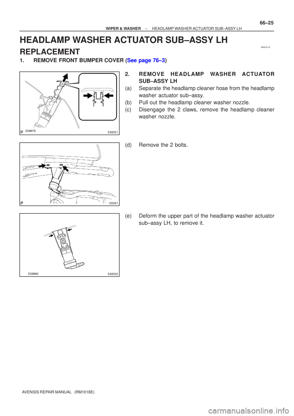
HEADLAMP WASHER ACTUATOR SUB±ASSY LH
REPLACEMENT
1.REMOVE FRONT BUMPER COVER (See page 76±3)
2. R E M O V E H E A D L A M P WA S H E R A C T U ATO RSUB±ASSY LH
(a) Separate the headlamp cleaner hose from the headlamp washer actuator sub±assy.
(b) Pull out the headlamp cleaner washer nozzle.
(c) Disengage the 2 claws, remove the headlamp cleaner washer nozzle.
(d) Remove the 2 bolts.
(e) Deform the upper part of the headlamp washer actuator sub±assy LH, to remove it.
Page 3153 of 5135
6804U±01
I35269
Engine Room No.2 Relay Block
Engine Room Relay Block
Glow Plug Relay AssyEngine Room No.3 Relay Block
Engine Room No.2 Relay Relay
Engine Room No.3 Relay Block
ENGINE:
3ZZ±FE:
1ZZ±FE:
2AZ±FSE:
1AZ±FSE:
1AZ±FE:
ENGINE:
1CD±FTV: w/o Discharge headlamp:
Headlamp Cleaner Control Relay
w/ Discharge headlamp:
Headlamp Cleaner Control Relay Assy
w/o Discharge headlamp:
Headlamp Cleaner Control Relay
w/ Discharge headlamp:
Headlamp Cleaner Control Relay Assy
Engine Room Relay Block
± WIRINGPOWER SOURCE
68±1
AVENSIS REPAIR MANUAL (RM1018E)
POWER SOURCE
LOCATION
Page 3225 of 5135

16.REMOVE CONSOLE PANEL SUB±ASSY UP")
B70029: 4 Clips
A/T Transaxle:
M/T Transaxle:
B66045Claw
±
INSTRUMENT PANEL/METER INSTRUMENT PANEL SUB±ASSY LOWER
71±15
AVENSIS REPAIR MANUAL (RM1018E)
16.REMOVE CONSOLE PANEL SUB±ASSY UPPER
(a)Using a moulding remover, disengage the 4 clips.
(b)Disconnect the connectors, and remove the console pan-
el sub±assy upper.
17.REMOVE INSTRUMENT CLUSTER FINISH PANEL SUB±ASSY CENTER (W/O RADIO) (See page 55±50)
18.REMOVE STEREO OPENING COVER W/BRACKET (W/O RADIO)
19.REMOVE RADIO RECEIVER ASSEMBLY W/BRACKET (See page 67±5)
20.REMOVE HORN BUTTON ASSY (See page 60±17)
21.REMOVE STEERING WHEEL ASSY (See page 50±9) SST09950±50013 (09951±05010, 09952±05010, 09953±05020, 09954±\
05021)
22.REMOVE HEADLAMP DIMMER SWITCH ASSY (See page 65±27)
23.REMOVE WINDSHIELD WIPER SWITCH ASSY (See page 66±24)
24.REMOVE INSTRUMENT PANEL UNDER COVERSUB±ASSY NO.1
(a)Remove the 2 screws .
(b)Disengage the claw and remove the instrument panel un- der cover sub±assy No.1.
25.REMOVE INSTRUMENT PANEL HOLE COVER (See page 60±54)
26.REMOVE INSTRUMENT PANEL AIR BAG ASSY (See page 60±54)
27.REMOVE STEERING COLUMN COVER LWR (See page 50±9)
Page 3393 of 5135

REPLACEMENT
HINT:
The installation is in the reverse order of the removal. However, when ther")
760WY±01
B67425
Claw
B67431
± EXTERIOR/INTERIOR TRIMFRONT BUMPER
76±3
AVENSIS REPAIR MANUAL (RM1018E)
REPLACEMENT
HINT:
The installation is in the reverse order of the removal. However, when there is a special point concerning
the installation, it is indicated.
1. REMOVE FRONT BUMPER COVER
(a) Put protective tape under the front fender.
HINT:
Because the spoiler covers LH and RH are assembled, remove
them together.
(b) Remove the spoiler.
(1) Remove the 9 screws and 6 claws.
(2) Remove the 6 retainers.
(3) Remove the spoiler covers LH and RH together.
(4) Remove the bolt and separate the spoiler cover RH
from the LH.
(c) Remove the 3 bolts and 2 clips.
(d) Using a screwdriver, disengage the 6 claws and remove
the bumper cover.
HINT:
Tape the screwdriver tip before use.
(e) w/ Fog lamp:
Disconnect the fog lamp connectors.
2. R E M O V E H E A D L A M P WA S H E R A C T U ATO R
SUB±ASSY LH (W/ HEADLAMP CLEANER)
(a) Remove the washer hose clip.
(b) Using a screwdriver, pry out the front washer nozzle.
HINT:
Tape the screwdriver tip before use.
(c) Remove the 2 screws and actuator.
3. REMOVE HEADLAMP WASHER ACTUATOR SUB±ASSY RH (W/ HEADLAMP CLEANER)
HINT:
Use the same procedures described for the LH side.
4. REMOVE INTERCOOLER COOLING AIR DUCT SUB±ASSY (W/ CAC 1CD±FTV ENGINE TYPE)
(a) Remove the 3 screws and air duct.
5. REMOVE FRONT BUMPER REINFORCEMENT SUB±ASSY
(a) Using a screwdriver, remove the wire harness.
(b) Remove the 8 bolts and reinforcement.
6. REMOVE FRONT BUMPER SIDE RETAINER LH
(a) Using a screwdriver, remove the 2 screws and retainer.
HINT:
Tape the screwdriver tip before use.
Page 3396 of 5135
B68229
w/ Headlamp Cleaner
Headlamp Washer
Actuator Sub±assy RH
Headlamp Washer
Actuator Sub±assy LH
Radiator Grille Lower
Front Bumper Cover Headlamp Washer
Nozzle Sub±assy LH Headlamp Washer
Nozzle Sub±assy RH
Front Spoiler
Cover LH Front Spoiler
Cover RH
76±2
± EXTERIOR/INTERIOR TRIMFRONT BUMPER
AVENSIS REPAIR MANUAL (RM1018E)
Page 5094 of 5135
71–")
B70029: 4 Clips
A/T Transaxle:
M/T Transaxle:
B80618
w/ Stereo Opening Cover:
w/o Stereo Opening Cover:
: 4 Clips
– INSTRUMENT PANEL/METERINSTRUMENT PANEL SUB–ASSY LOWER (From
February, 2004)71–9
AVENSIS REPAIR MANUAL SUPPLEMENT
(RM1098E)
16. REMOVE CONSOLE PANEL SUB–ASSY UPPER
(a) Using a moulding remover, disengage the 4 clips.
(b) Disconnect the connectors, and remove the console pan-
el sub–assy upper.
17. REMOVE INSTRUMENT CLUSTER FINISH PANEL
SUB–ASSY CENTER W/BRACKET (W/O RADIO)
(a) Remove the 4 bolts.
(b) Using a moulding remover, disengage the 4 clips.
(c) Disconnect the connector and remove the instrument
cluster finish panel sub–assy center w/ blacket.
18. REMOVE RADIO RECEIVER ASSEMBLY W/BRACKET (W/ RADIO) (See Pub. No. RM1018E, page
67–5)
19. REMOVE HORN BUTTON ASSY (See Pub. No. RM1018E, page 60–17)
20. REMOVE STEERING WHEEL ASSY (See Pub. No. RM1018E, page 50–9)
SST 09950–50013 (09951–05010, 09952–05010, 09953–05020, 09954–05021)
21. REMOVE HEADLAMP DIMMER SWITCH ASSY (See Pub. No. RM1018E, page 65–27)
22. REMOVE WINDSHIELD WIPER SWITCH ASSY (See Pub. No. RM1018E, page 66–24)