Page 3054 of 5135
±
LIGHTING LIGHTING SYSTEM
65±3
AVENSIS REPAIR MANUAL (RM1018E)
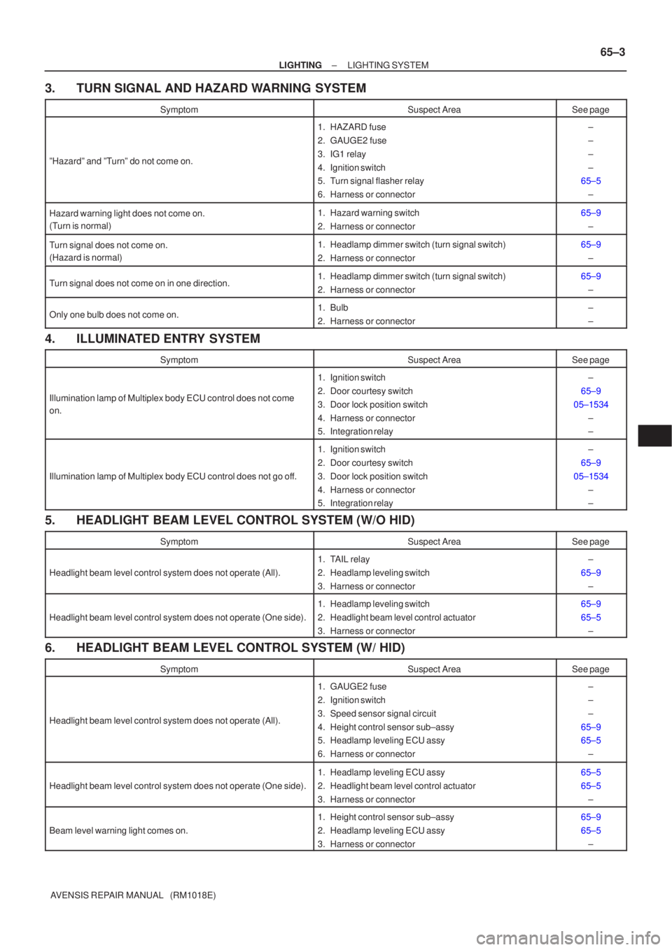
3. TURN SIGNAL AND HAZARD WARNING SYSTEM
SymptomSuspect AreaSee page
ºHazardº and ºTurnº do not come on.
1. HAZARD fuse
2. GAUGE2 fuse
3. IG1 relay
4. Ignition switch
5. Turn signal flasher relay
6. Harness or connector±
±
±
±
65±5
±
Hazard warning light does not come on.
(Turn is normal)1. Hazard warning switch
2. Harness or connector65±9±
Turn signal does not come on.
(Hazard is normal)1. Headlamp dimmer switch (turn signal switch)
2. Harness or connector65±9±
Turn signal does not come on in one direction.1. Headlamp dimmer switch (turn signal switch)
2. Harness or connector65±9±
Only one bulb does not come on.1. Bulb
2. Harness or connector±
±
4. ILLUMINATED ENTRY SYSTEM
SymptomSuspect AreaSee page
Illumination lamp of Multiplex body ECU control does not come
on.
1. Ignition switch
2. Door courtesy switch
3. Door lock position switch
4. Harness or connector
5. Integration relay±
65±9
05±1534 ±
±
Illumination lamp of Multiplex body ECU control does not go off.
1. Ignition switch
2. Door courtesy switch
3. Door lock position switch
4. Harness or connector
5. Integration relay±
65±9
05±1534 ±
±
5. HEADLIGHT BEAM LEVEL CONTROL SYSTEM (W/O HID)
SymptomSuspect AreaSee page
Headlight beam level control system does not operate (All).
1. TAIL relay
2. Headlamp leveling switch
3. Harness or connector±
65±9 ±
Headlight beam level control system does not operate (One side).
1. Headlamp leveling switch
2. Headlight beam level control actuator
3. Harness or connector65±9
65±5±
6. HEADLIGHT BEAM LEVEL CONTROL SYSTEM (W/ HID)
SymptomSuspect AreaSee page
Headlight beam level control system does not operate (All).
1. GAUGE2 fuse
2. Ignition switch
3. Speed sensor signal circuit
4. Height control sensor sub±assy
5. Headlamp leveling ECU assy
6. Harness or connector±
±
±
65±9
65±5 ±
Headlight beam level control system does not operate (One side).
1. Headlamp leveling ECU assy
2. Headlight beam level control actuator
3. Harness or connector65±5
65±5±
Beam level warning light comes on.
1. Height control sensor sub±assy
2. Headlamp leveling ECU assy
3. Harness or connector65±9
65±5±
Page 3056 of 5135
650NC±02
± LIGHTINGLIGHTING SYSTEM
65±1
AVENSIS REPAIR MANUAL (RM1018E)
LIGHTING SYSTEM
PRECAUTION
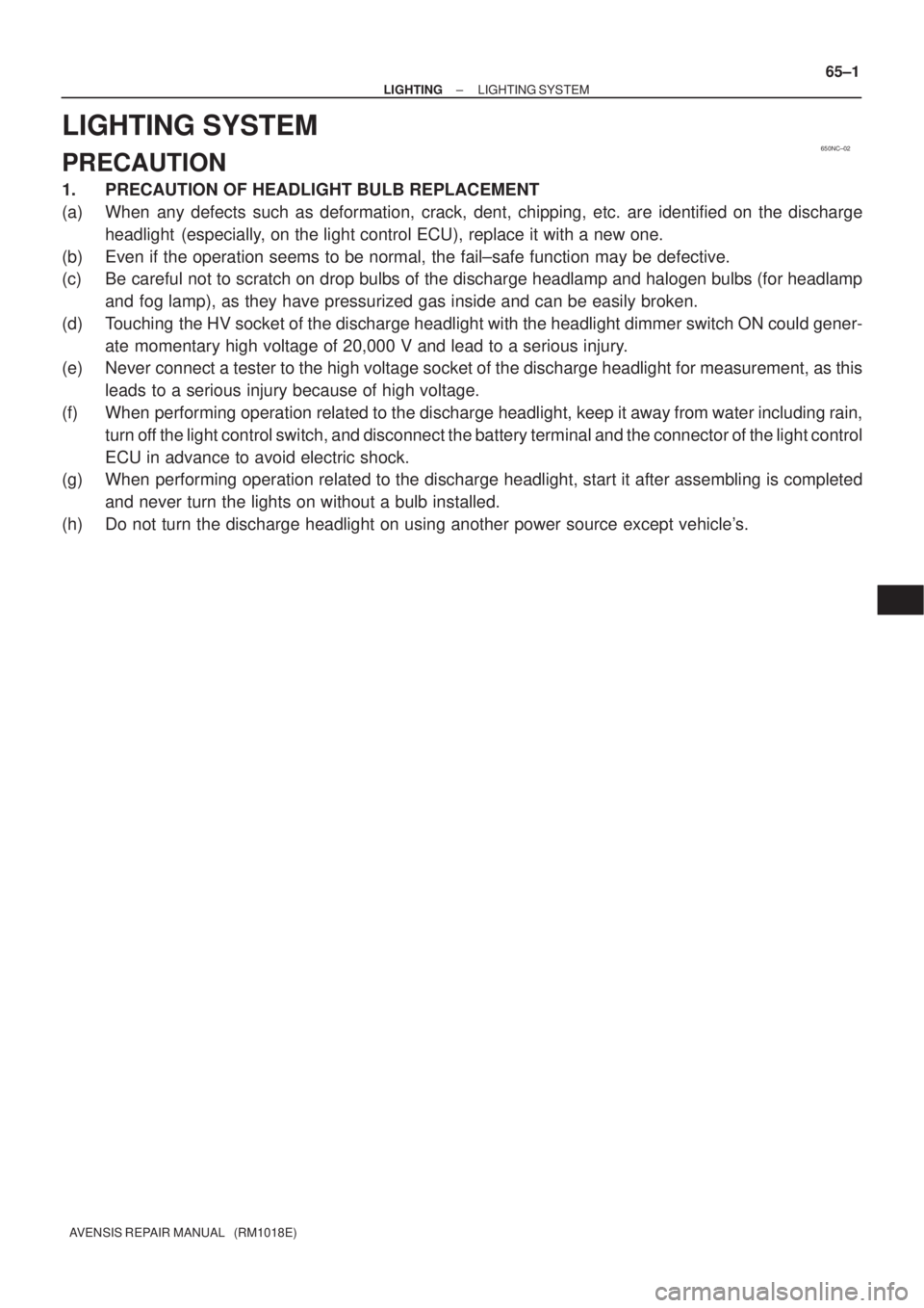
1. PRECAUTION OF HEADLIGHT BULB REPLACEMENT
(a) When any defects such as deformation, crack, dent, chipping, etc. are identified on the discharge
headlight (especially, on the light control ECU), replace it with a new one.
(b) Even if the operation seems to be normal, the fail±safe function may be defective.
(c) Be careful not to scratch on drop bulbs of the discharge headlamp and halogen bulbs (for headlamp
and fog lamp), as they have pressurized gas inside and can be easily broken.
(d) Touching the HV socket of the discharge headlight with the headlight dimmer switch ON could gener-
ate momentary high voltage of 20,000 V and lead to a serious injury.
(e) Never connect a tester to the high voltage socket of the discharge headlight for measurement, as this
leads to a serious injury because of high voltage.
(f) When performing operation related to the discharge headlight, keep it away from water including rain,
turn off the light control switch, and disconnect the battery terminal and the connector of the light control
ECU in advance to avoid electric shock.
(g) When performing operation related to the discharge headlight, start it after assembling is completed
and never turn the lights on without a bulb installed.
(h) Do not turn the discharge headlight on using another power source except vehicle's.
Page 3088 of 5135
E68141
E67355
Wagon Type:
Automatic Stop Position
Automatic Stop Position Lift Back Type:170� � 3�
160� � 3�
E68111
66±10
± WIPER & WASHERWIPER AND WASHER SYSTEM
AVENSIS REPAIR MANUAL (RM1018E)
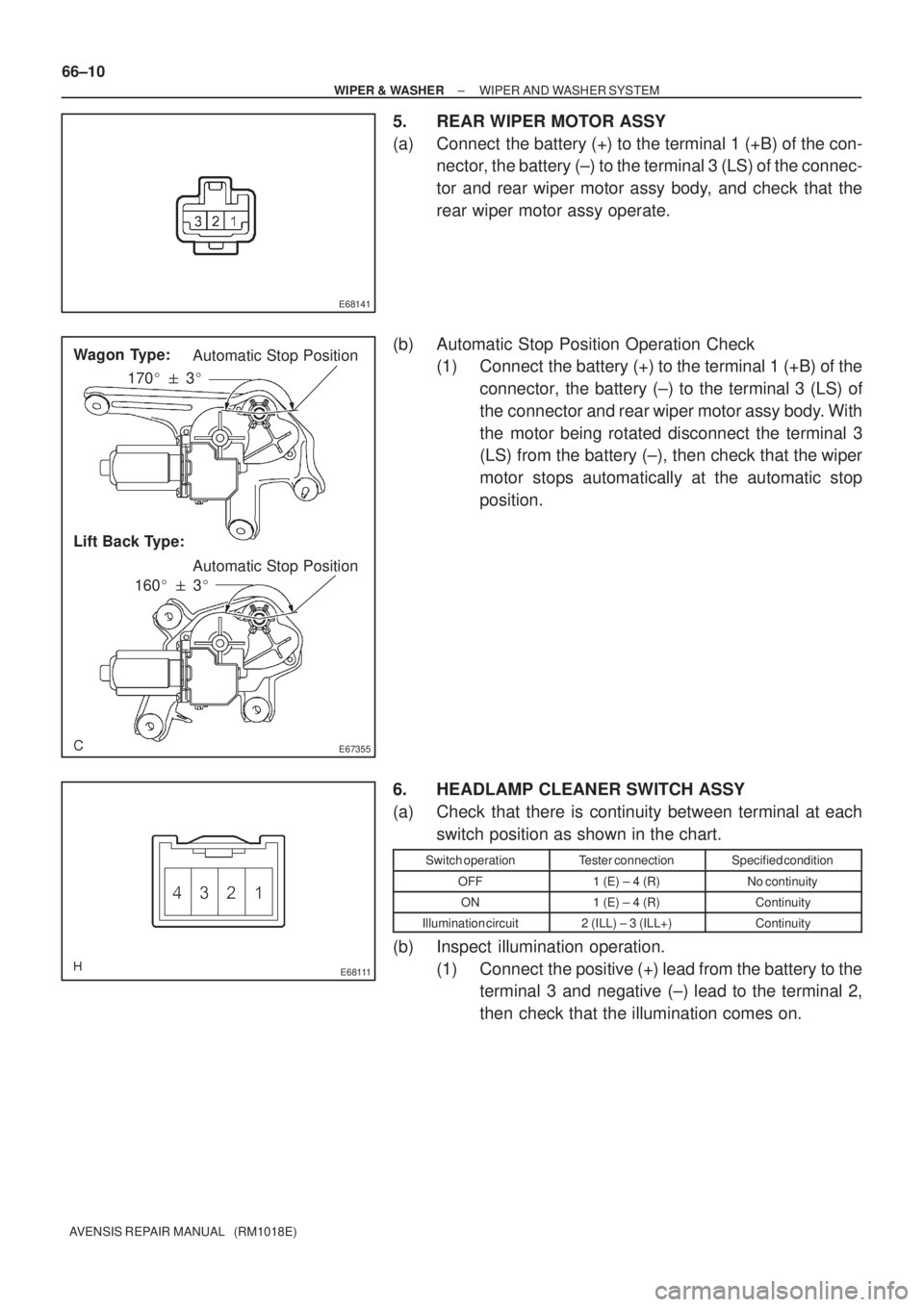
5. REAR WIPER MOTOR ASSY
(a) Connect the battery (+) to the terminal 1 (+B) of the con-
nector, the battery (±) to the terminal 3 (LS) of the connec-
tor and rear wiper motor assy body, and check that the
rear wiper motor assy operate.
(b) Automatic Stop Position Operation Check
(1) Connect the battery (+) to the terminal 1 (+B) of the
connector, the battery (±) to the terminal 3 (LS) of
the connector and rear wiper motor assy body. With
the motor being rotated disconnect the terminal 3
(LS) from the battery (±), then check that the wiper
motor stops automatically at the automatic stop
position.
6. HEADLAMP CLEANER SWITCH ASSY
(a) Check that there is continuity between terminal at each
switch position as shown in the chart.
Switch operationTester connectionSpecified condition
OFF1 (E) ± 4 (R)No continuity
ON1 (E) ± 4 (R)Continuity
Illumination circuit2 (ILL) ± 3 (ILL+)Continuity
(b) Inspect illumination operation.
(1) Connect the positive (+) lead from the battery to the
terminal 3 and negative (±) lead to the terminal 2,
then check that the illumination comes on.
Page 3089 of 5135
E68112
������E69072
± WIPER & WASHERWIPER AND WASHER SYSTEM
66±11
AVENSIS REPAIR MANUAL (RM1018E)
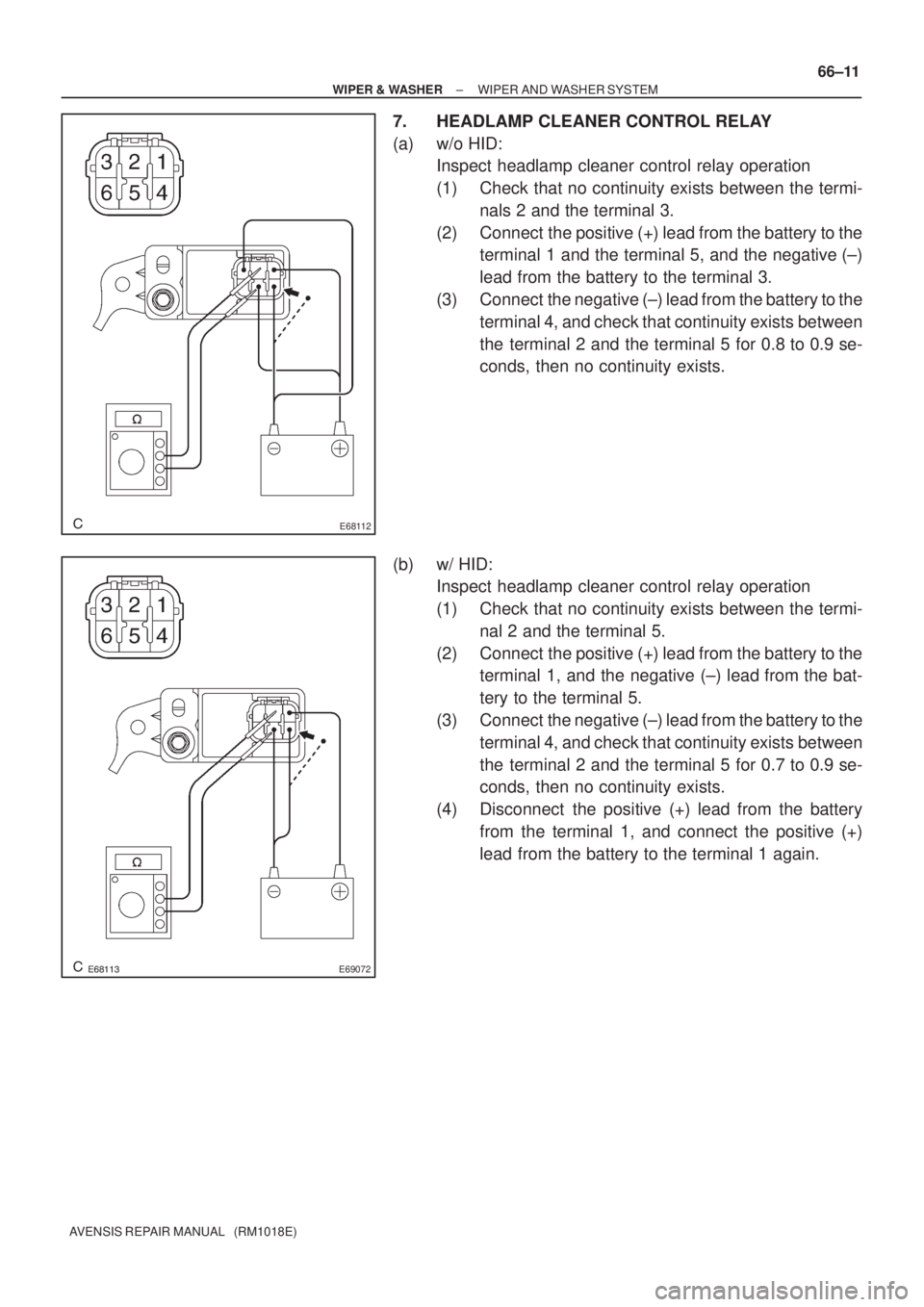
7. HEADLAMP CLEANER CONTROL RELAY
(a) w/o HID:
Inspect headlamp cleaner control relay operation
(1) Check that no continuity exists between the termi-
nals 2 and the terminal 3.
(2) Connect the positive (+) lead from the battery to the
terminal 1 and the terminal 5, and the negative (±)
lead from the battery to the terminal 3.
(3) Connect the negative (±) lead from the battery to the
terminal 4, and check that continuity exists between
the terminal 2 and the terminal 5 for 0.8 to 0.9 se-
conds, then no continuity exists.
(b) w/ HID:
Inspect headlamp cleaner control relay operation
(1) Check that no continuity exists between the termi-
nal 2 and the terminal 5.
(2) Connect the positive (+) lead from the battery to the
terminal 1, and the negative (±) lead from the bat-
tery to the terminal 5.
(3) Connect the negative (±) lead from the battery to the
terminal 4, and check that continuity exists between
the terminal 2 and the terminal 5 for 0.7 to 0.9 se-
conds, then no continuity exists.
(4) Disconnect the positive (+) lead from the battery
from the terminal 1, and connect the positive (+)
lead from the battery to the terminal 1 again.
Page 3091 of 5135
660CL±01
E67356
E67356
E67352
E68115
66±4
± WIPER & WASHERWIPER AND WASHER SYSTEM
AVENSIS REPAIR MANUAL (RM1018E)
ON±VEHICLE INSPECTION
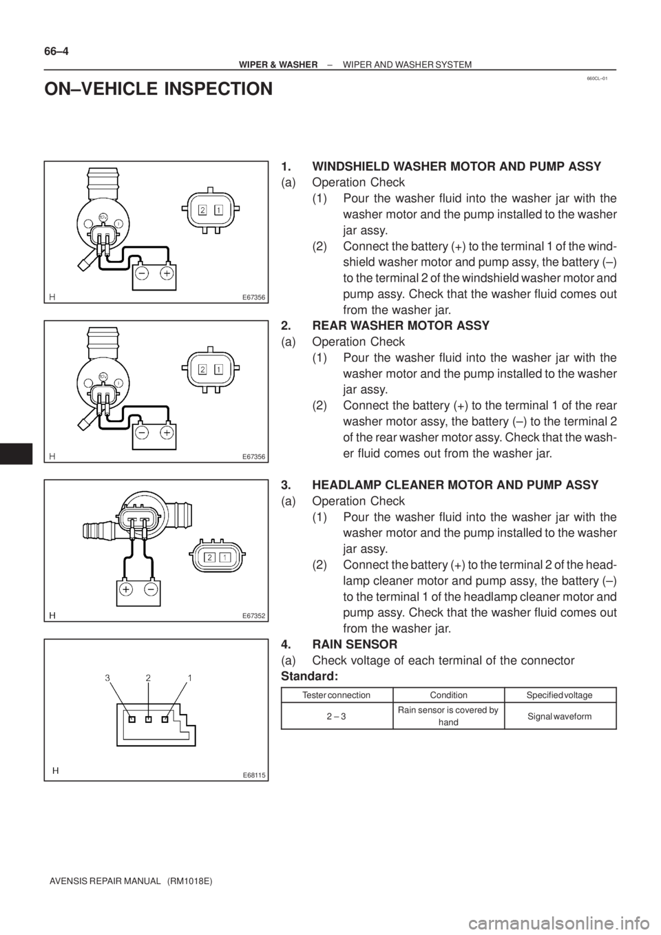
1. WINDSHIELD WASHER MOTOR AND PUMP ASSY
(a) Operation Check
(1) Pour the washer fluid into the washer jar with the
washer motor and the pump installed to the washer
jar assy.
(2) Connect the battery (+) to the terminal 1 of the wind-
shield washer motor and pump assy, the battery (±)
to the terminal 2 of the windshield washer motor and
pump assy. Check that the washer fluid comes out
from the washer jar.
2. REAR WASHER MOTOR ASSY
(a) Operation Check
(1) Pour the washer fluid into the washer jar with the
washer motor and the pump installed to the washer
jar assy.
(2) Connect the battery (+) to the terminal 1 of the rear
washer motor assy, the battery (±) to the terminal 2
of the rear washer motor assy. Check that the wash-
er fluid comes out from the washer jar.
3. HEADLAMP CLEANER MOTOR AND PUMP ASSY
(a) Operation Check
(1) Pour the washer fluid into the washer jar with the
washer motor and the pump installed to the washer
jar assy.
(2) Connect the battery (+) to the terminal 2 of the head-
lamp cleaner motor and pump assy, the battery (±)
to the terminal 1 of the headlamp cleaner motor and
pump assy. Check that the washer fluid comes out
from the washer jar.
4. RAIN SENSOR
(a) Check voltage of each terminal of the connector
Standard:
Tester connectionConditionSpecified voltage
2 ± 3Rain sensor is covered by
handSignal waveform
Page 3094 of 5135
±
WIPER & WASHER WIPER AND WASHER SYSTEM
66±3
AVENSIS REPAIR MANUAL (RM1018E)
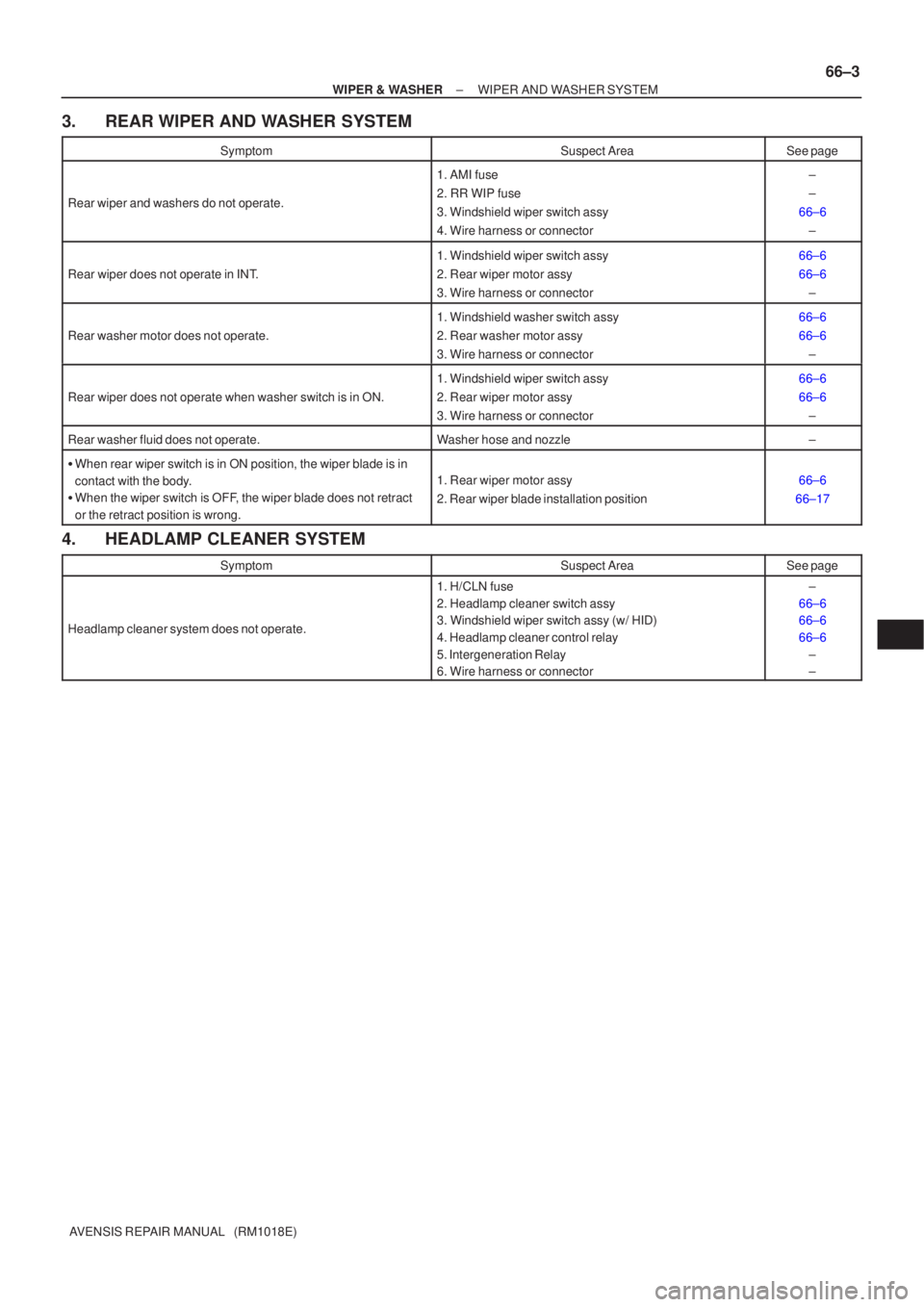
3. REAR WIPER AND WASHER SYSTEM
SymptomSuspect AreaSee page
Rear wiper and washers do not operate.
1. AMI fuse
2. RR WIP fuse
3. Windshield wiper switch assy
4. Wire harness or connector±
±
66±6 ±
Rear wiper does not operate in INT.
1. Windshield wiper switch assy
2. Rear wiper motor assy
3. Wire harness or connector66±6
66±6±
Rear washer motor does not operate.
1. Windshield washer switch assy
2. Rear washer motor assy
3. Wire harness or connector66±6
66±6±
Rear wiper does not operate when washer switch is in ON.
1. Windshield wiper switch assy
2. Rear wiper motor assy
3. Wire harness or connector66±6
66±6±
Rear washer fluid does not operate.Washer hose and nozzle±
�When rear wiper switch is in ON position, the wiper blade is in
contact with the body.
� When the wiper switch is OFF, the wiper blade does not retract
or the retract position is wrong.
1. Rear wiper motor assy
2. Rear wiper blade installation position66±6
66±17
4. HEADLAMP CLEANER SYSTEM
SymptomSuspect AreaSee page
Headlamp cleaner system does not operate.
1. H/CLN fuse
2. Headlamp cleaner switch assy
3. Windshield wiper switch assy (w/ HID)
4. Headlamp cleaner control relay
5. Intergeneration Relay
6. Wire harness or connector±
66±6
66±6
66±6 ±
±
Page 3096 of 5135
650T5±01
I35250
65±30
±
LIGHTING HEADLAMP LEVELING ECU ASSY
AVENSIS REPAIR MANUAL (RM1018E)
HEADLAMP LEVELING ECU ASSY
REPLACEMENT
1. REMOVE GLOVE COMPARTMENT DOOR ASSY (LHD STEERING POSITION TYPE) (See page 71±11)
2.REMOVE FUSE BOX OPENING COVER (RHD STEERING POSITION TYPE) (See page 71±11)
3. REMOVE LIGHT CONTROL ECU
(a) Disconnect the connector.
(b) Remove the bolt and headlamp leveling ECU assy.
4. INSTALL LIGHT CONTROL ECU
(a) Install the headlamp leveling ECU assy with the bolt.
(b) Connect the connector.
Page 3099 of 5135
650T2±01
I35251
I35252Claw
± LIGHTINGHEADLAMP DIMMER SWITCH ASSY
65±27
AVENSIS REPAIR MANUAL (RM1018E)
HEADLAMP DIMMER SWITCH ASSY
REPLACEMENT
1. SEPARATE STEERING COLUMN COVER LWR
(a) Remove the 3 screws and steering column cover LWR.
2. REMOVE HEADLAMP DIMMER SWITCH ASSY
(a) Disconnect the connector.
(b) Release the claw and pull out the headlamp dimmer
switch assy.