Page 3102 of 5135
650SZ±01
������������������I35249
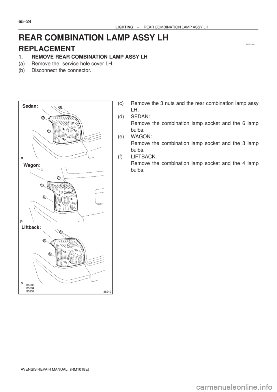
Sedan:
Wagon:
Liftback: 65±24
± LIGHTINGREAR COMBINATION LAMP ASSY LH
AVENSIS REPAIR MANUAL (RM1018E)
REAR COMBINATION LAMP ASSY LH
REPLACEMENT
1. REMOVE REAR COMBINATION LAMP ASSY LH
(a) Remove the service hole cover LH.
(b) Disconnect the connector.
(c) Remove the 3 nuts and the rear combination lamp assy
LH.
(d) SEDAN:
Remove the combination lamp socket and the 6 lamp
bulbs.
(e) WAGON:
Remove the combination lamp socket and the 3 lamp
bulbs.
(f) LIFTBACK:
Remove the combination lamp socket and the 4 lamp
bulbs.
Page 3104 of 5135
650SX±01
I35237Clamp
I35228
65±22
±
LIGHTING FOG LAMP ASSY LH
AVENSIS REPAIR MANUAL (RM1018E)
FOG LAMP ASSY LH
REPLACEMENT
1.REMOVE FRONT BUMPER COVER (See page 76±3) 2.REMOVE FOG LAMP ASSY LH
(a)Disconnect the connector.
(b)Remove the 2 screws.
(c)Release the claw fitting, then remove the fog lamp assyLH.
(d)Remove the fog lamp bulb as shown in the illustration.
3.ADJUST FOG LIGHT AIM (See page 65±23)
4. CHECK FOG LIGHT AIM
Page 3108 of 5135
650SU±01
I35241
I35242
I35243
I35254
65±16
±
LIGHTING HEADLAMP UNIT LH
AVENSIS REPAIR MANUAL (RM1018E)
REPLACEMENT
1.REMOVE FRONT SPOILER COVER LH (See page 76±3)
2.REMOVE FRONT SPOILER COVER RH (See page 76±3)
3.REMOVE FRONT BUMPER COVER (See page 76±3) 4. REMOVE HEAD LIGHT ASSY
(a) Disconnect the connector.
(b) Remove the 2 screws.
(c) Remove the headlamp assy and disengage the claw asshown in the illustration.
5. REMOVE HEADLAMP, NO.1 BULB (HALOGEN HEAD LAMP)
(a) Release the lock of the set spring and remove the head- lamp bulb No.1.
6. REMOVE DISCHARGE HEADLAMP BULB (DISCHARGE HEAD LAMP)
(a) Rotate the bulb socket cover in the direction of the arrow
and pull it of backward of the vehicle.
Page 3109 of 5135

(b) Release the lock of the set spring and remove the dis-
charge headlamp bulb.
7. REMOVE HEADL")
I35255
I35244
I35229
I35245
I36703
± LIGHTINGHEADLAMP UNIT LH
65±17
AVENSIS REPAIR MANUAL (RM1018E)
(b) Release the lock of the set spring and remove the dis-
charge headlamp bulb.
7. REMOVE HEADLAMP, NO.2 BULB
(a) Remove the headlamp socket cover.
(b) Release the lock of the set spring and remove the head-
lamp bulb No.2.
8. REMOVE CLEARANCE LAMP BULB
(a) Remove the clearance lamp socket and the clearance
lamp bulb as shown in the illustration.
(b) Remove the clearance lamp bulb from the clearance lamp
socket.
9. REMOVE FRONT TURN SIGNAL LAMP BULB
(a) Remove the front turn signal lamp socket and the front
turn signal lamp bulb as shown in the illustration.
10. REMOVE HEADLAMP PROTECTOR RETAINER
HINT:
When only the installation part of the headlamp unit assy LH is
damaged, it can be repaired inexpensively by using a head-
lamp protector retainer. In this case, however, the headlamp
unit assy LH itself should not be damaged.
(a) Cut off the part shaded in the illustration and file it smooth.
NOTICE:
After cutting off the part roughly, place the headlamp pro-
tector retainer against the bosses, and gradually file any in-
terfering part until the proper condition for installation is
made.
Page 3111 of 5135
650ST±01
I35226
Headlamp No.2 BulbBulb Socket
Socket Cover
Bulb Socket
Back Cover
Headlamp No.1 Bulb
Front Turn Signal Lamp Bulb Clearance Lamp Bulb Halogen Headlamp:
Discharge Headlamp:
Headlamp No.2 Bulb
Clearance Lamp Bulb
Bulb Socket
Back Cover
Front Turn Signal Lamp Bulb
Socket Cover
Discharge Headlamp Bulb
Headlamp Protector Retainer
± LIGHTINGHEADLAMP UNIT LH
65±15
AVENSIS REPAIR MANUAL (RM1018E)
HEADLAMP UNIT LH
COMPONENTS
Page 3252 of 5135

8 (E) 3 (DEF)
B69288
1 2 3 4 5 6 7 8
E ILL+
70±50
± WINDSHIELD/WINDOWGLASS/MIRRORWINDOW DEFOGGER SYSTEM
AVENSIS REPA")
700TD±01
B67055
1 2 3 4 5 6 7 8
E
ILL+
B67056
1.4 W
Test Bulb Switch ON
5 (IG)
8 (E) 3 (DEF)
B69288
1 2 3 4 5 6 7 8
E ILL+
70±50
± WINDSHIELD/WINDOWGLASS/MIRRORWINDOW DEFOGGER SYSTEM
AVENSIS REPAIR MANUAL (RM1018E)
INSPECTION
1. INSPECT REAR WINDOW DEFOGGER SWITCH
(LHD Models)
(a) Check that the defogger switch illuminates.
Standard:
Measurement ConditionSpecified Condition
Battery positive (+) � 5 (ILL+)
Battery negative (±) �8 (E)Illuminates
If the result is not as specified, replace the switch assy or bulb.
(b) Inspect operation of the defogger timer.
(1) Connect the positive (+) lead from the battery to ter-
minal 3 and the negative (±) lead to terminal 8.
(2) Connect the positive (+) lead from the battery to ter-
minal 4 through a 1.4 W test bulb.
(3) Push the rear window defogger switch ON, check
the switch and the test bulb illuminate for 12 ± 18
minutes, and then they go off.
If the result is not as specified, replace the switch assy.
2. INSPECT REAR WINDOW DEFOGGER SWITCH
(RHD Models)
(a) Check that the defogger switch illuminates.
Standard:
Measurement ConditionSpecified Condition
Battery positive (+) � 4 (ILL+)
Battery negative (±) � 1 (E)Illuminates
If the result is not as specified, replace the switch assy or bulb.
Page 3253 of 5135

6 (DEF)
1 (E)
B67057
B67058
1.4 W Test Bulb
Switch ON1 (IG)
6 (D)
3 (E)
± WINDSHIELD/WINDOWGLASS/MIRRORWINDOW DEFOGGER SYSTEM
70±51
AVENSIS REPAIR MANUAL (")
B69289
1.4 W
Test Bulb Switch ON
5 (IG)
6 (DEF)
1 (E)
B67057
B67058
1.4 W Test Bulb
Switch ON1 (IG)
6 (D)
3 (E)
± WINDSHIELD/WINDOWGLASS/MIRRORWINDOW DEFOGGER SYSTEM
70±51
AVENSIS REPAIR MANUAL (RM1018E)
(b) Inspect operation of the defogger timer.
(1) Connect the positive (+) lead from the battery to ter-
minal 6 and the negative (±) lead to terminal 1.
(2) Connect the positive (+) lead from the battery to ter-
minal 5 through a 1.4 W test bulb.
(3) Push the rear window defogger switch ON, check
that the switch and the test bulb illuminate for 12 ±
18 minutes, and then they go off.
If the result is not as specified, replace the switch assy.
3. INSPECT FR WIPER DEICER SWITCH (W/ DEICER)
(a) check that the wiper deicer switch illuminates.
Standard:
Measurement ConditionSpecified Condition
Battery positive (+) � 1
Battery negative (±) � 4Illuminates
If the result is not as specified, replace the switch or bulb.
(b) Inspect operation of the wiper deicer timer.
(1) Connect the positive (+) lead from the battery to ter-
minal 6 and the negative (±) lead to terminal 3.
(2) Connect the positive (+) lead from the battery to ter-
minal 1 through a 1.4 W test bulb.
(3) Push the wiper deicer switch ON, check that the
switch and the test bulb illuminate for 12 ± 18 min-
utes, and then they go off.
If the result is not as specified, replace the switch.
Page 3334 of 5135

65�
18� 0 0 0.42 ± 0.28 4.08 ± 2.72
ON OFF 65�
B70591
1 21 2 3 4 5 A
B
± SEATSEAT HEATER SYSTEM
72±37
AVENSIS REPAIR MANUAL (RM1018E)
INSPECT")
720JH±01
������
������
B70589
A
B
1 21 2 3 4 5
(k�)
65�
18� 0 0 0.42 ± 0.28 4.08 ± 2.72
ON OFF 65�
B70591
1 21 2 3 4 5 A
B
± SEATSEAT HEATER SYSTEM
72±37
AVENSIS REPAIR MANUAL (RM1018E)
INSPECTION
1. LH side:
INSPECT SEAT HEATER SWITCH
(a) Check the seat heater switch resistance.
Tester ConnectionSwitch PositionSpecified Condition
OFF10 k�or higher
B±2 ± B±4ON
(Minimum ± Maximum)Below 1 �
OFF10 k�or higher
B±2 ± B±3ON
(Minimum ± Maximum)Refer to illustration
If the continuity is not as specified, replace the switch.
(b) Turn the seat heater switch ON and check the seat heater
switch indicator illuminates.
Tester ConnectionSpecified Condition
Battery positive voltage�B±2
Battery negative voltage�B±5Illuminates
If the result is not as specified, replace the switch.
(c) Check the seat heater switch illuminates.
Tester ConnectionSpecified Condition
Battery positive voltage�B±1
Battery negative voltage�B±5Illuminates
If the result is not as specified, replace the switch or bulb.

FOG LAMP ASSY LH
REPLACEMENT
1.REMOVE FRONT BUMPER COVER (See page 76±3) 2.REMOVE FOG LAMP ASSY LH
(")

REPLACEMENT
1.REMOVE FRONT SPOILER COVER LH (See page 76±3)
2.REMOVE FRONT SPOILER COVER RH")
