Page 1317 of 5135
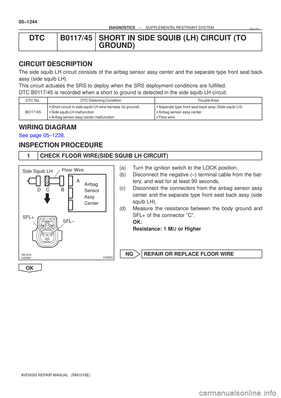
\b�����\b�����H42853
Airbag
Sensor
Assy
Center
SFL±
SFL+
Side Squib LH
Floor Wire
A
B
C
D
05±1244
±
DIAGNOSTICS SUPPLEMENTAL RESTRAINT SYSTEM
AVENSIS REPAIR MANUAL (RM1018E)
DTC B0117/45 SHORT IN SIDE SQUIB (LH) CIRCUIT (TO GROUND)
CIRCUIT DESCRIPTION
The side squib LH circuit consists of the airbag sensor assy center and the\
separate type front seat back
assy (side squib LH).
This circuit actuates the SRS to deploy when the SRS deployment conditio\
ns are fulfilled.
DTC B0117/45 is recorded when a short to ground is detected in the side squib L\
H circuit.
DTC No.DTC Detecting ConditionTrouble Area
B0117/45
�Short circuit in side squib LH wire harness (to ground)
� Side squib LH malfunction
� Airbag sensor assy center malfunction�Separate type front seat back assy (Side squib LH)
� Airbag sensor assy center
� Floor wire
WIRING DIAGRAM
See page 05±1238.
INSPECTION PROCEDURE
1 CHECK FLOOR WIRE(SIDE SQUIB LH CIRCUIT)
(a) Turn the ignition switch to the LOCK position.
(b) Disconnect the negative (±) terminal cable from the bat-
tery, and wait for at least 90 seconds.
(c) Disconnect the connectors from the airbag sensor assy center and the separate type front seat back assy (side
squib LH).
(d) Measure the resistance between the body ground and
SFL+ of the connector ºCº.
OK:
Resistance: 1 M � or Higher
NG REPAIR OR REPLACE FLOOR WIRE
OK
054LX±06
Page 1320 of 5135
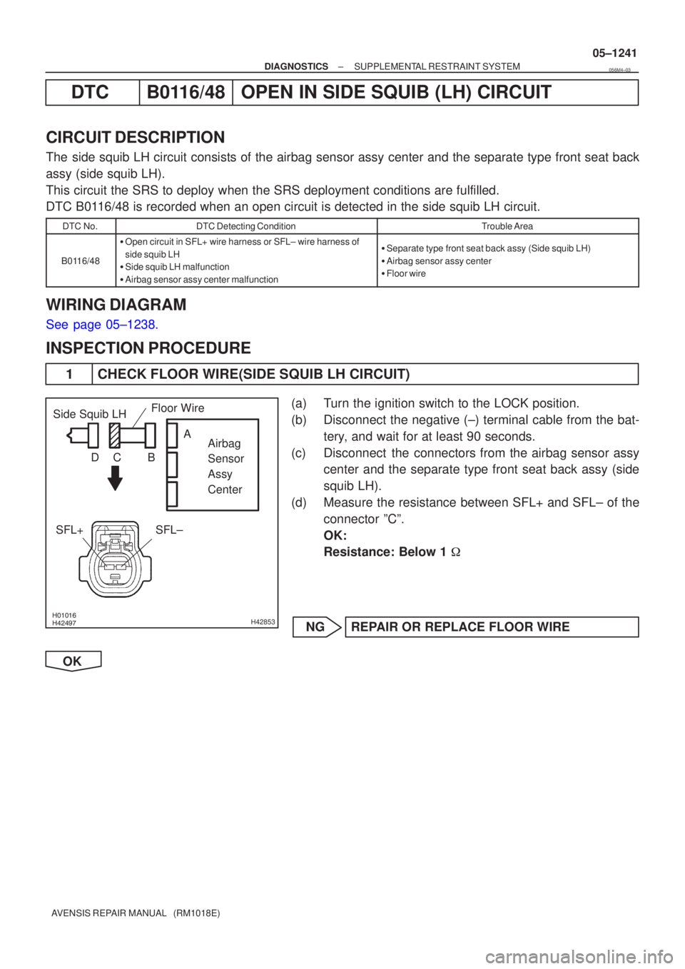
\b�����\b�����H42853
Side Squib LHAirbag
Sensor
Assy
Center
SFL+SFL±Floor Wire
B
DC A
±
DIAGNOSTICS SUPPLEMENTAL RESTRAINT SYSTEM
05±1241
AVENSIS REPAIR MANUAL (RM1018E)
DTCB0116/48OPEN IN SIDE SQUIB (LH) CIRCUIT
CIRCUIT DESCRIPTION
The side squib LH circuit consists of the airbag sensor assy center and the\
separate type front seat back
assy (side squib LH).
This circuit the SRS to deploy when the SRS deployment conditions are fu\
lfilled.
DTC B0116/48 is recorded when an open circuit is detected in the side squib LH \
circuit.
DTC No.DTC Detecting ConditionTrouble Area
B0116/48
�Open circuit in SFL+ wire harness or SFL± wire harness of
side squib LH
� Side squib LH malfunction
� Airbag sensor assy center malfunction�Separate type front seat back assy (Side squib LH)
� Airbag sensor assy center
� Floor wire
WIRING DIAGRAM
See page 05±1238.
INSPECTION PROCEDURE
1 CHECK FLOOR WIRE(SIDE SQUIB LH CIRCUIT)
(a) Turn the ignition switch to the LOCK position.
(b) Disconnect the negative (±) terminal cable from the bat-
tery, and wait for at least 90 seconds.
(c) Disconnect the connectors from the airbag sensor assy center and the separate type front seat back assy (side
squib LH).
(d) Measure the resistance between SFL+ and SFL± of the connector ºCº.
OK:
Resistance: Below 1 �
NG REPAIR OR REPLACE FLOOR WIRE
OK
056M4±03
Page 1323 of 5135
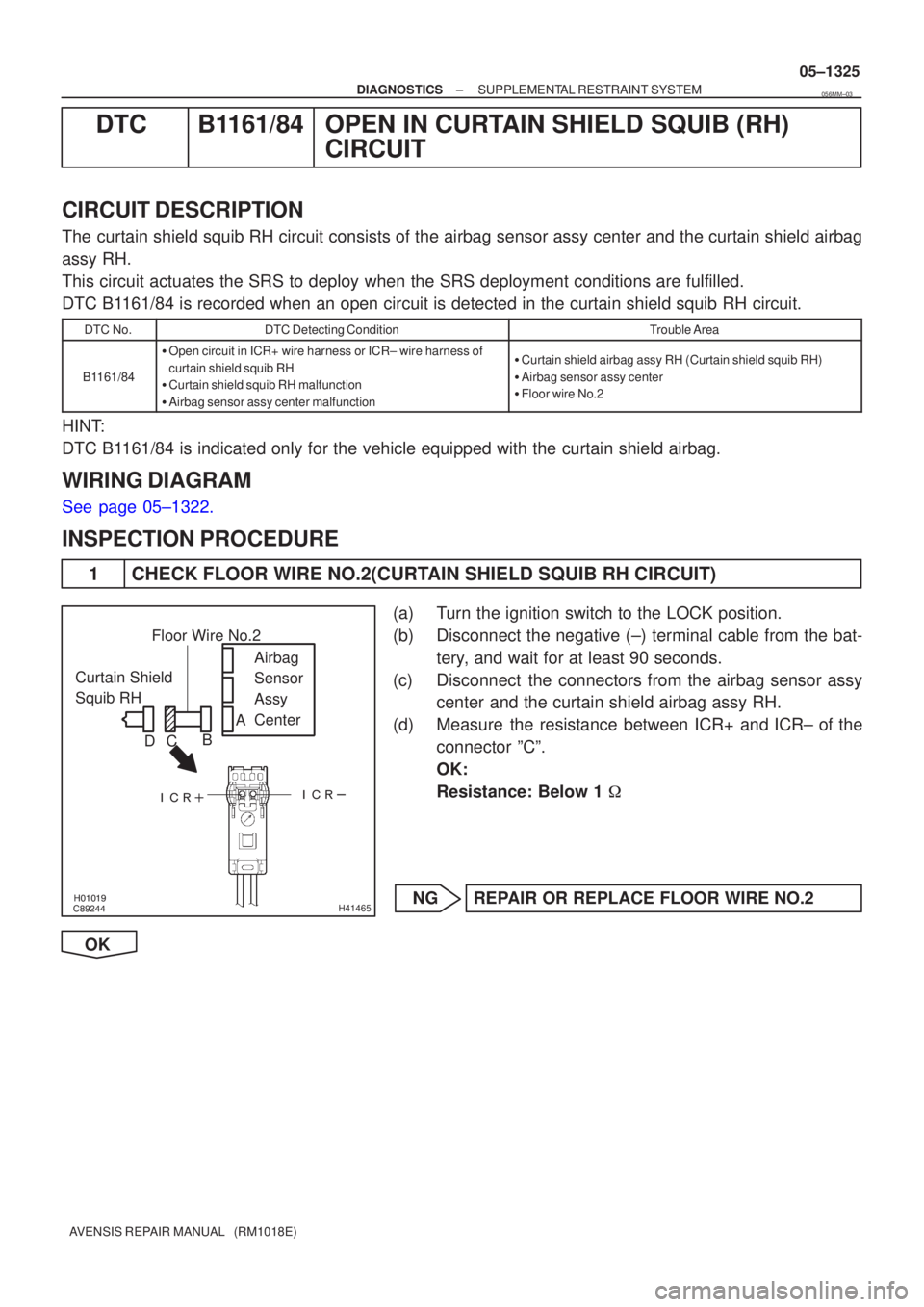
\b�����
������
����
����
H41465
Curtain Shield
Squib RH Airbag
Sensor
Assy
Center
Floor Wire No.2
A
B
C
D
±
DIAGNOSTICS SUPPLEMENTAL RESTRAINT SYSTEM
05±1325
AVENSIS REPAIR MANUAL (RM1018E)
DTCB1161/84OPEN IN CURTAIN SHIELD SQUIB (RH)
CIRCUIT
CIRCUIT DESCRIPTION
The curtain shield squib RH circuit consists of the airbag sensor assy cent\
er and the curtain shield airbag
assy RH.
This circuit actuates the SRS to deploy when the SRS deployment conditio\
ns are fulfilled.
DTC B1161/84 is recorded when an open circuit is detected in the curtain shiel\
d squib RH circuit.
DTC No.DTC Detecting ConditionTrouble Area
B1161/84
�Open circuit in ICR+ wire harness or ICR± wire harness of
curtain shield squib RH
� Curtain shield squib RH malfunction
� Airbag sensor assy center malfunction�Curtain shield airbag assy RH (Curtain shield squib RH)
� Airbag sensor assy center
� Floor wire No.2
HINT:
DTC B1161/84 is indicated only for the vehicle equipped with the curtain shiel\
d airbag.
WIRING DIAGRAM
See page 05±1322.
INSPECTION PROCEDURE
1 CHECK FLOOR WIRE NO.2(CURTAIN SHIELD SQUIB RH CIRCUIT)
(a) Turn the ignition switch to the LOCK position.
(b) Disconnect the negative (±) terminal cable from the bat-
tery, and wait for at least 90 seconds.
(c) Disconnect the connectors from the airbag sensor assy center and the curtain shield airbag assy RH.
(d) Measure the resistance between ICR+ and ICR± of the connector ºCº.
OK:
Resistance: Below 1 �
NG REPAIR OR REPLACE FLOOR WIRE NO.2
OK
056MM±03
Page 1326 of 5135
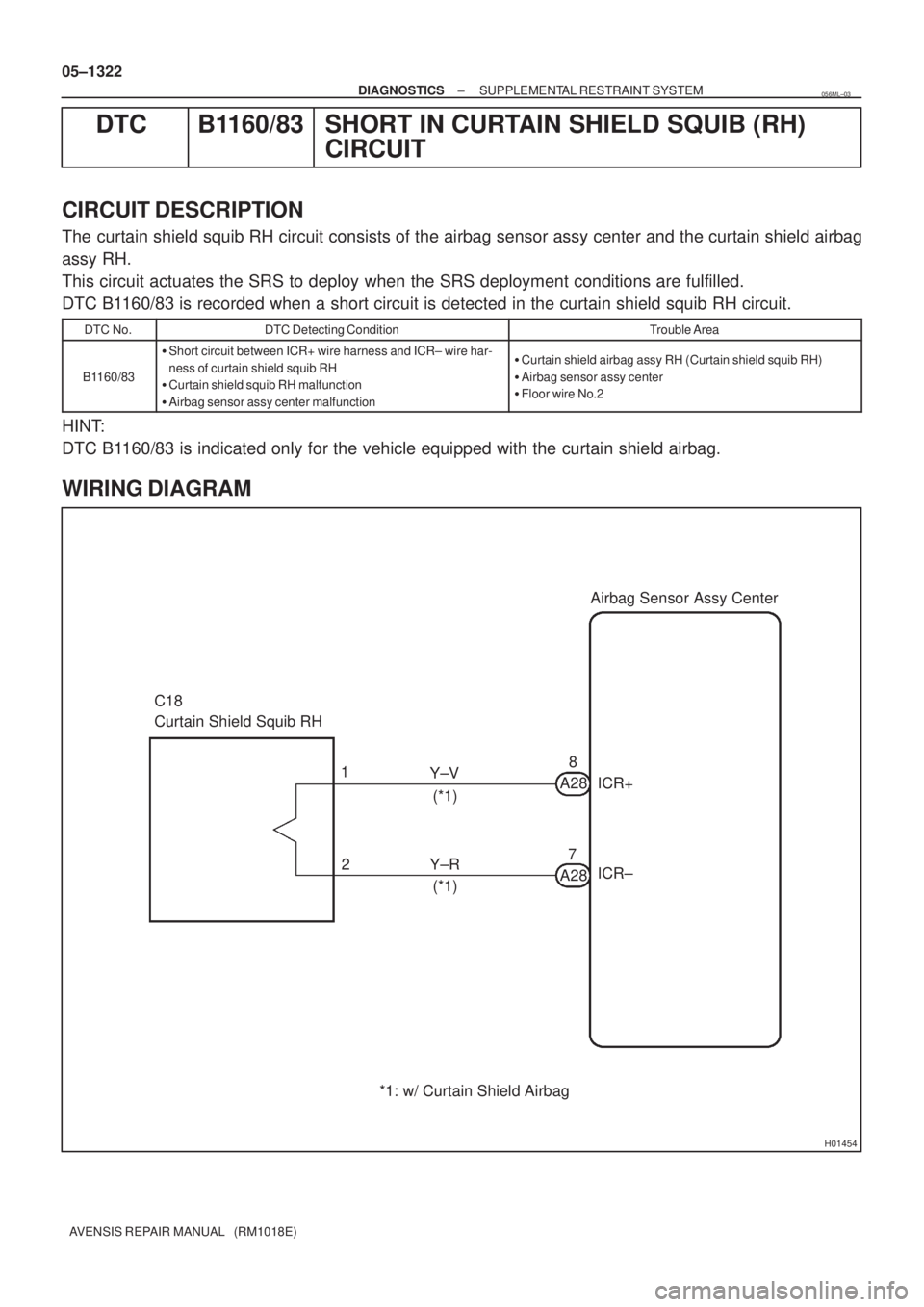
H01454
Airbag Sensor Assy Center
C18
Curtain Shield Squib RH
8
A28 ICR+ Y±V
7
A28ICR± Y±R 1
2(*1)
(*1)
*1: w/ Curtain Shield Airbag 05±1322
± DIAGNOSTICSSUPPLEMENTAL RESTRAINT SYSTEM
AVENSIS REPAIR MANUAL (RM1018E)
DTC B1160/83 SHORT IN CURTAIN SHIELD SQUIB (RH)
CIRCUIT
CIRCUIT DESCRIPTION
The curtain shield squib RH circuit consists of the airbag sensor assy center and the curtain shield airbag
assy RH.
This circuit actuates the SRS to deploy when the SRS deployment conditions are fulfilled.
DTC B1160/83 is recorded when a short circuit is detected in the curtain shield squib RH circuit.
DTC No.DTC Detecting ConditionTrouble Area
B1160/83
�Short circuit between ICR+ wire harness and ICR± wire har-
ness of curtain shield squib RH
�Curtain shield squib RH malfunction
�Airbag sensor assy center malfunction�Curtain shield airbag assy RH (Curtain shield squib RH)
�Airbag sensor assy center
�Floor wire No.2
HINT:
DTC B1160/83 is indicated only for the vehicle equipped with the curtain shield airbag.
WIRING DIAGRAM
056ML±03
Page 1329 of 5135
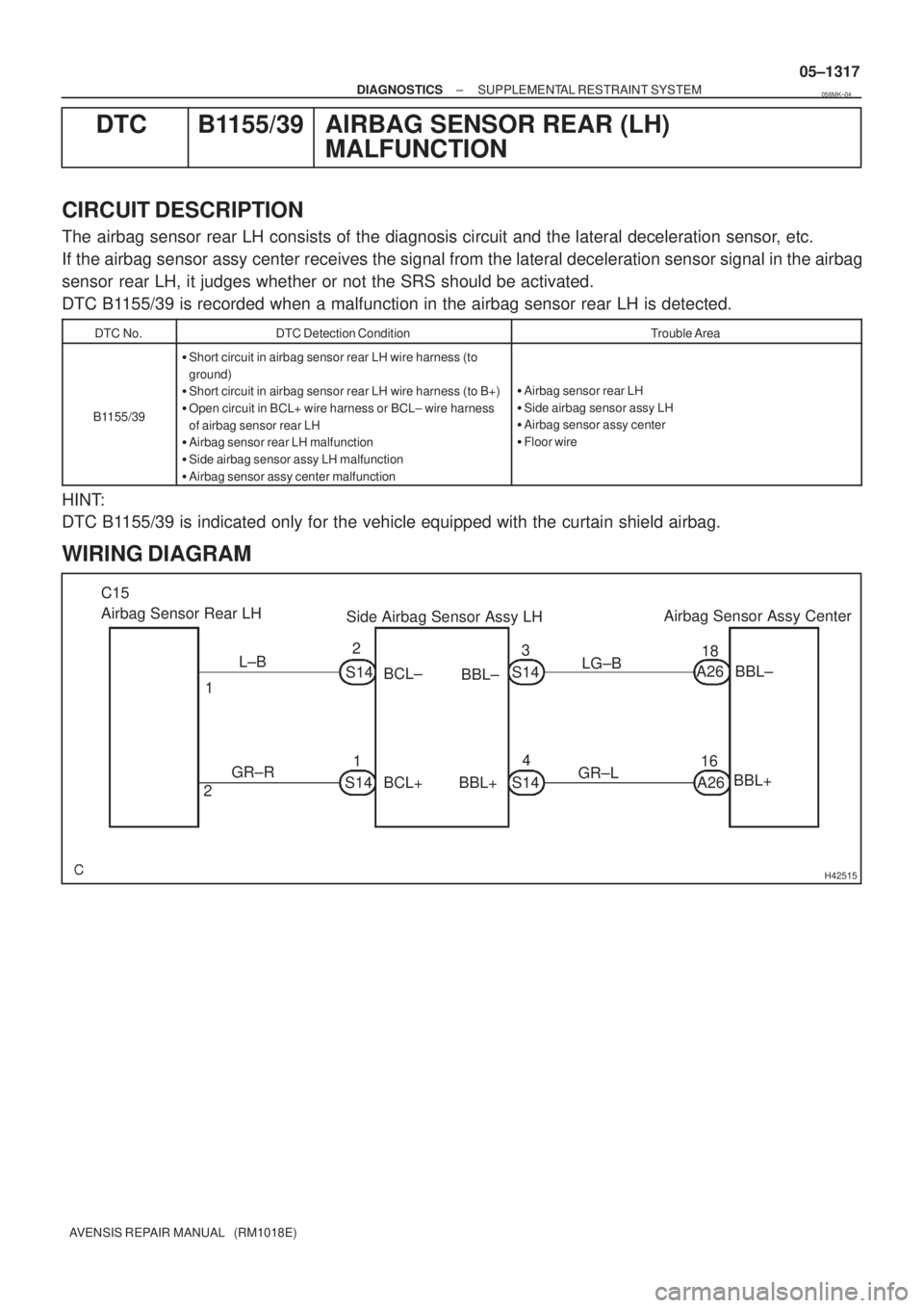
H42515
Side Airbag Sensor Assy LHAirbag Sensor Assy Center C15
Airbag Sensor Rear LH
L±B
1S14
BCL±
BBL±
22
1
S14 S14 GR±R
BCL+ BBL+S143
4LG±B
GR±LBBL±
BBL+ A2618
A2616
± DIAGNOSTICSSUPPLEMENTAL RESTRAINT SYSTEM
05±1317
AVENSIS REPAIR MANUAL (RM1018E)
DTC B1155/39 AIRBAG SENSOR REAR (LH)
MALFUNCTION
CIRCUIT DESCRIPTION
The airbag sensor rear LH consists of the diagnosis circuit and the lateral deceleration sensor, etc.
If the airbag sensor assy center receives the signal from the lateral deceleration sensor signal in the airbag
sensor rear LH, it judges whether or not the SRS should be activated.
DTC B1155/39 is recorded when a malfunction in the airbag sensor rear LH is detected.
DTC No.DTC Detection ConditionTrouble Area
B1155/39
�Short circuit in airbag sensor rear LH wire harness (to
ground)
�Short circuit in airbag sensor rear LH wire harness (to B+)
�Open circuit in BCL+ wire harness or BCL± wire harness
of airbag sensor rear LH
�Airbag sensor rear LH malfunction
�Side airbag sensor assy LH malfunction
�Airbag sensor assy center malfunction
�Airbag sensor rear LH
�Side airbag sensor assy LH
�Airbag sensor assy center
�Floor wire
HINT:
DTC B1155/39 is indicated only for the vehicle equipped with the curtain shield airbag.
WIRING DIAGRAM
056MK±04
Page 1334 of 5135
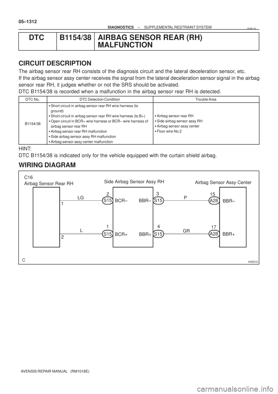
H42515
C16
Airbag Sensor Rear RHSide Airbag Sensor Assy RH
Airbag Sensor Assy Center
BBR±
BBR+ P
GR BCR±
BCR+BBR±
BBR+ LG
L 1
2S1523
4 1
17 15
A28
S15S15
S15A28 05±1312
± DIAGNOSTICSSUPPLEMENTAL RESTRAINT SYSTEM
AVENSIS REPAIR MANUAL (RM1018E)
DTC B1154/38 AIRBAG SENSOR REAR (RH)
MALFUNCTION
CIRCUIT DESCRIPTION
The airbag sensor rear RH consists of the diagnosis circuit and the lateral deceleration sensor, etc.
If the airbag sensor assy center receives the signal from the lateral deceleration sensor signal in the airbag
sensor rear RH, it judges whether or not the SRS should be activated.
DTC B1154/38 is recorded when a malfunction in the airbag sensor rear RH is detected.
DTC No.DTC Detection ConditionTrouble Area
B1154/38
�Short circuit in airbag sensor rear RH wire harness (to
ground)
�Short circuit in airbag sensor rear RH wire harness (to B+)
�Open circuit in BCR+ wire harness or BCR± wire harness of
airbag sensor rear RH
�Airbag sensor rear RH malfunction
�Side airbag sensor assy RH malfunction
�Airbag sensor assy center malfunction
�Airbag sensor rear RH
�Side airbag sensor assy RH
�Airbag sensor assy center
�Floor wire No.2
HINT:
DTC B1154/38 is indicated only for the vehicle equipped with the curtain shield airbag.
WIRING DIAGRAM
05A6E±03
Page 1339 of 5135
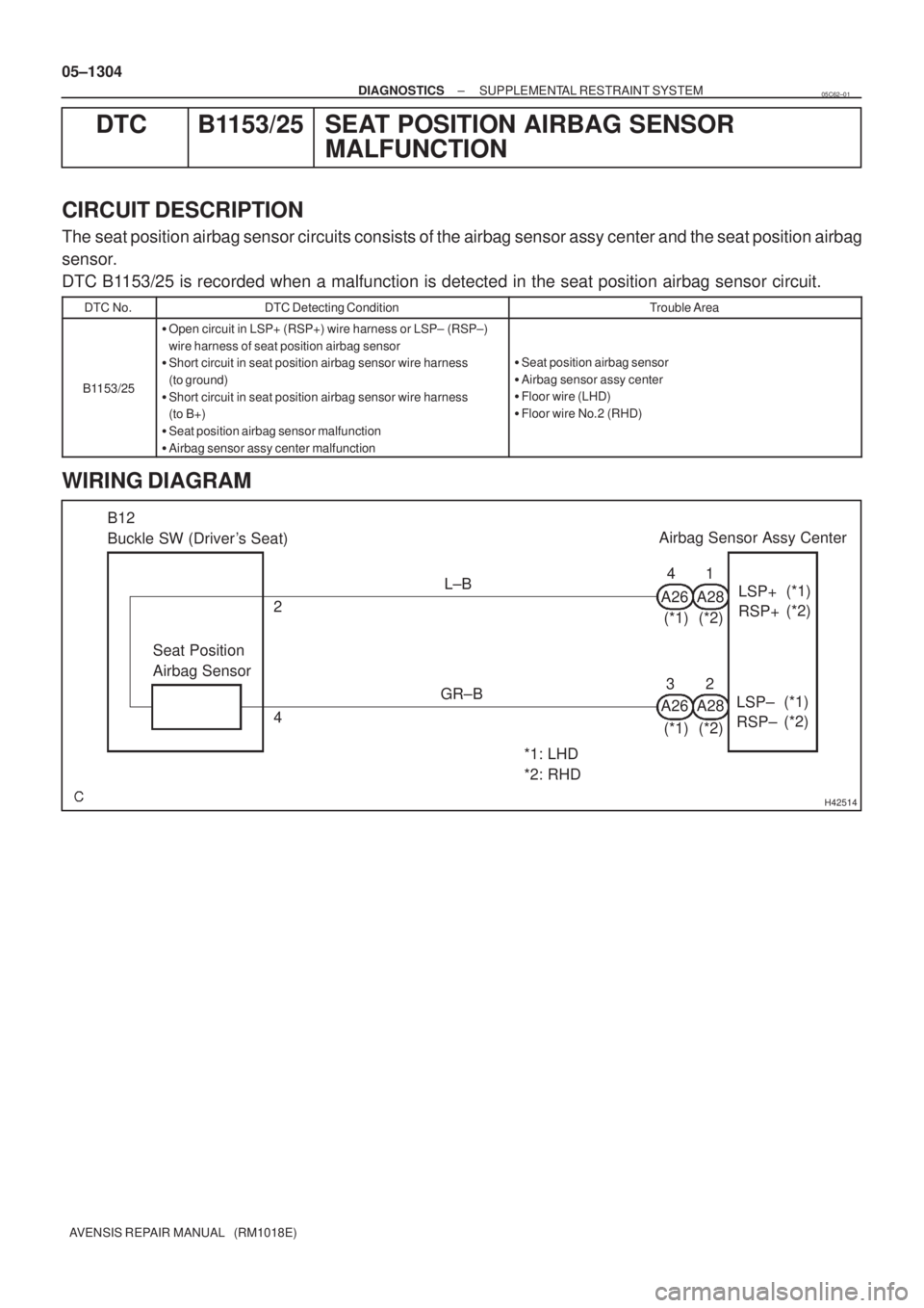
H42514
B12
Buckle SW (Driver's Seat)Airbag Sensor Assy Center
Seat Position
Airbag Sensor2
4L±B
GR±B
*1: LHD
*2: RHDLSP+
RSP+(*1)
(*2) 4
A261
A28
LSP±
RSP±(*1)
(*2) A26 A2832 (*1) (*2)
(*1) (*2) 05±1304
± DIAGNOSTICSSUPPLEMENTAL RESTRAINT SYSTEM
AVENSIS REPAIR MANUAL (RM1018E)
DTC B1153/25 SEAT POSITION AIRBAG SENSOR
MALFUNCTION
CIRCUIT DESCRIPTION
The seat position airbag sensor circuits consists of the airbag sensor assy center and the seat position airbag
sensor.
DTC B1153/25 is recorded when a malfunction is detected in the seat position airbag sensor circuit.
DTC No.DTC Detecting ConditionTrouble Area
B1153/25
�Open circuit in LSP+ (RSP+) wire harness or LSP± (RSP±)
wire harness of seat position airbag sensor
�Short circuit in seat position airbag sensor wire harness
(to ground)
�Short circuit in seat position airbag sensor wire harness
(to B+)
�Seat position airbag sensor malfunction
�Airbag sensor assy center malfunction
�Seat position airbag sensor
�Airbag sensor assy center
�Floor wire (LHD)
�Floor wire No.2 (RHD)
WIRING DIAGRAM
05C62±01
Page 1347 of 5135
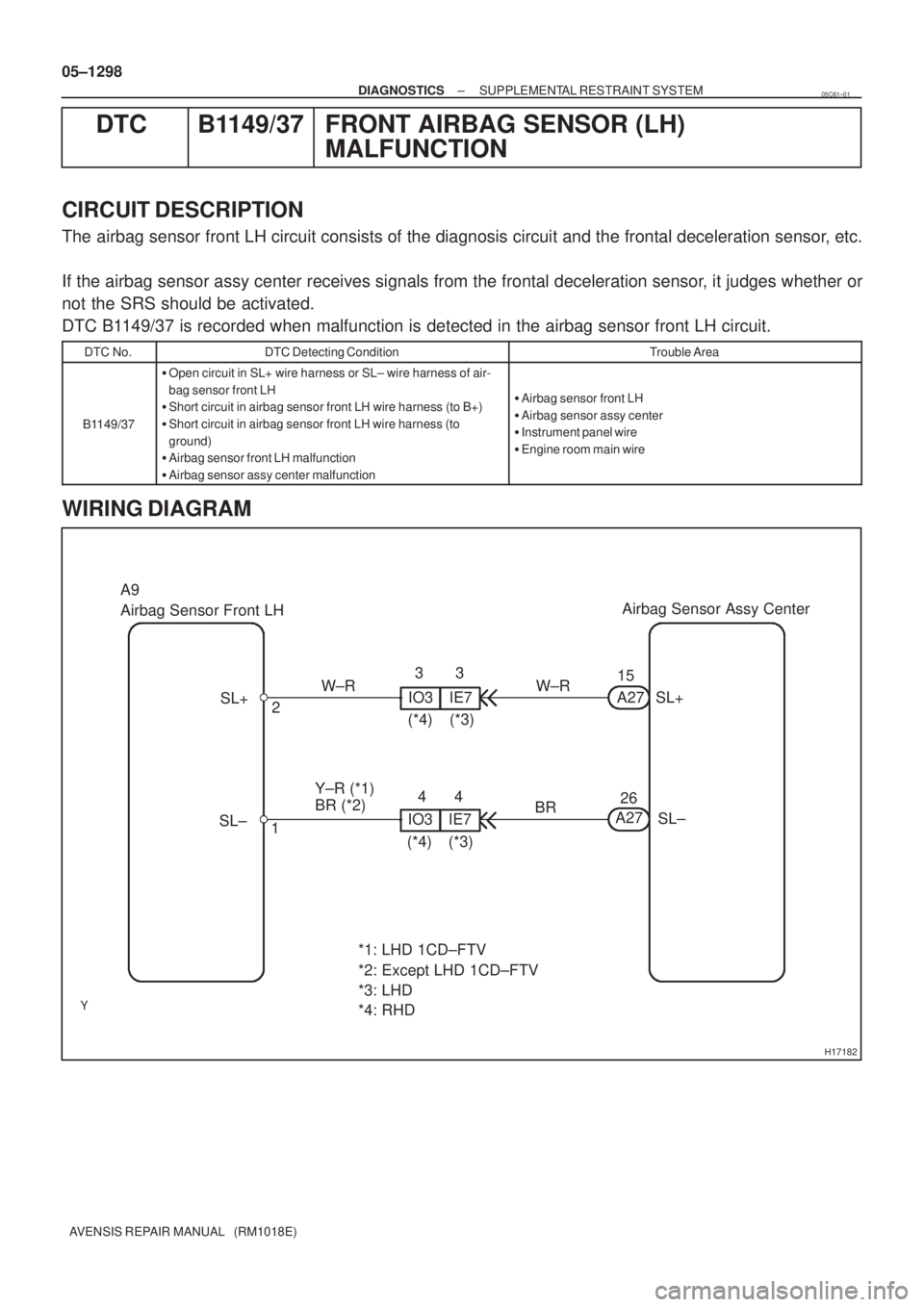
H17182
Airbag Sensor Assy Center
SL+
SL± A27
A2715
26 IO3
4 3
2
1 SL+
SL± A9
Airbag Sensor Front LH
W±R
BR IE73
4
IO3 IE7
(*3) (*4)(*3) (*4)
BR (*2) Y±R (*1)
*1: LHD 1CD±FTV
*2: Except LHD 1CD±FTV W±R
*3: LHD
*4: RHD 05±1298
± DIAGNOSTICSSUPPLEMENTAL RESTRAINT SYSTEM
AVENSIS REPAIR MANUAL (RM1018E)
DTC B1149/37 FRONT AIRBAG SENSOR (LH)
MALFUNCTION
CIRCUIT DESCRIPTION
The airbag sensor front LH circuit consists of the diagnosis circuit and the frontal deceleration sensor, etc.
If the airbag sensor assy center receives signals from the frontal deceleration sensor, it judges whether or
not the SRS should be activated.
DTC B1149/37 is recorded when malfunction is detected in the airbag sensor front LH circuit.
DTC No.DTC Detecting ConditionTrouble Area
B1149/37
�Open circuit in SL+ wire harness or SL± wire harness of air-
bag sensor front LH
�Short circuit in airbag sensor front LH wire harness (to B+)
�Short circuit in airbag sensor front LH wire harness (to
ground)
�Airbag sensor front LH malfunction
�Airbag sensor assy center malfunction
�Airbag sensor front LH
�Airbag sensor assy center
�Instrument panel wire
�Engine room main wire
WIRING DIAGRAM
05C61±01