Page 3835 of 5135
A56053
Width
45�25�
Z03988
45�
70�
A57105Contacting Width
A09537
14±30
± ENGINE MECHANICALCYLINDER HEAD ASSY (1CD±FTV)
1CD±FTV ENGINE REPAIR MANUAL (RM927E)
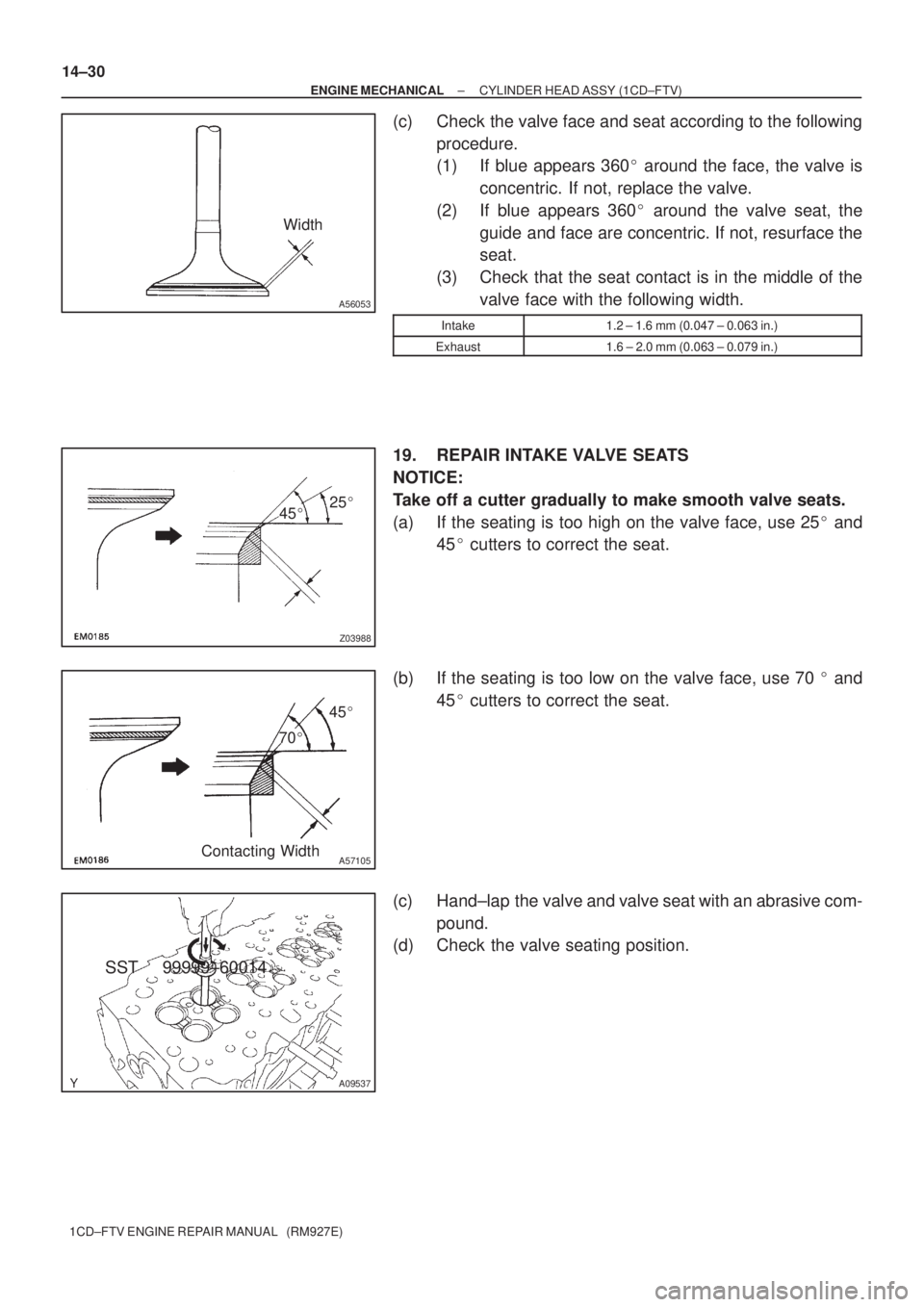
(c) Check the valve face and seat according to the following
procedure.
(1) If blue appears 360� around the face, the valve is
concentric. If not, replace the valve.
(2) If blue appears 360� around the valve seat, the
guide and face are concentric. If not, resurface the
seat.
(3) Check that the seat contact is in the middle of the
valve face with the following width.
Intake1.2 ± 1.6 mm (0.047 ± 0.063 in.)
Exhaust1.6 ± 2.0 mm (0.063 ± 0.079 in.)
19. REPAIR INTAKE VALVE SEATS
NOTICE:
Take off a cutter gradually to make smooth valve seats.
(a) If the seating is too high on the valve face, use 25� and
45� cutters to correct the seat.
(b) If the seating is too low on the valve face, use 70 � and
45� cutters to correct the seat.
(c) Hand±lap the valve and valve seat with an abrasive com-
pound.
(d) Check the valve seating position.
SST 99999±60014
Page 3836 of 5135
45�25�
Z03988
45�
65�
A57106
A56679
EM2196
A09544
± ENGINE MECHANICALCYLINDER HEAD ASSY (1CD±FTV)
14±31
1CD±FTV ENGINE REPAIR MANUAL (RM927E)
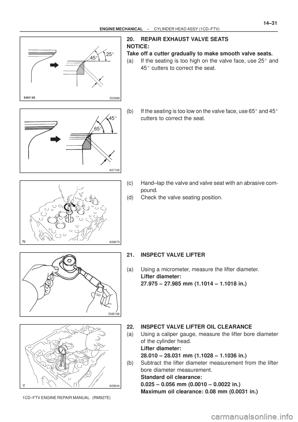
20. REPAIR EXHAUST VALVE SEATS
NOTICE:
Take off a cutter gradually to make smooth valve seats.
(a) If the seating is too high on the valve face, use 25� and
45� cutters to correct the seat.
(b) If the seating is too low on the valve face, use 65� and 45�
cutters to correct the seat.
(c) Hand±lap the valve and valve seat with an abrasive com-
pound.
(d) Check the valve seating position.
21. INSPECT VALVE LIFTER
(a) Using a micrometer, measure the lifter diameter.
Lifter diameter:
27.975 ± 27.985 mm (1.1014 ± 1.1018 in.)
22. INSPECT VALVE LIFTER OIL CLEARANCE
(a) Using a caliper gauge, measure the lifter bore diameter
of the cylinder head.
Lifter diameter:
28.010 ± 28.031 mm (1.1028 ± 1.1036 in.)
(b) Subtract the lifter diameter measurement from the lifter
bore diameter measurement.
Standard oil clearance:
0.025 ± 0.056 mm (0.0010 ± 0.0022 in.)
Maximum oil clearance: 0.08 mm (0.0031 in.)
Page 3860 of 5135
A57103
Plate Washer
Hexagon
Wrench
(8mm)
A62592
SST
B08252
B09792
Spring
Convex
14±18
± ENGINE MECHANICALPARTIAL ENGINE ASSY (1CD±FTV)
1CD±FTV ENGINE REPAIR MANUAL (RM927E)
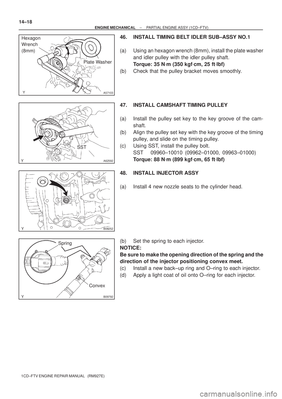
46. INSTALL TIMING BELT IDLER SUB±ASSY NO.1
(a) Using an hexagon wrench (8mm), install the plate washer
and idler pulley with the idler pulley shaft.
Torque: 35 N�m (350 kgf�cm, 25 ft�lbf)
(b) Check that the pulley bracket moves smoothly.
47. INSTALL CAMSHAFT TIMING PULLEY
(a) Install the pulley set key to the key groove of the cam-
shaft.
(b) Align the pulley set key with the key groove of the timing
pulley, and slide on the timing pulley.
(c) Using SST, install the pulley bolt.
SST 09960±10010 (09962±01000, 09963±01000)
Torque: 88 N�m (899 kgf�cm, 65 ft�lbf)
48. INSTALL INJECTOR ASSY
(a) Install 4 new nozzle seats to the cylinder head.
(b) Set the spring to each injector.
NOTICE:
Be sure to make the opening direction of the spring and the
direction of the injector positioning convex meet.
(c) Install a new back±up ring and O±ring to each injector.
(d) Apply a light coat of oil onto O±ring for each injector.
Page 4577 of 5135
A09656
A79144
A85755
11−48
−
FUEL INJECTOR ASSY (1CD −FTV)(From September, 2003)
AVENSIS Supplement (RM1045E)
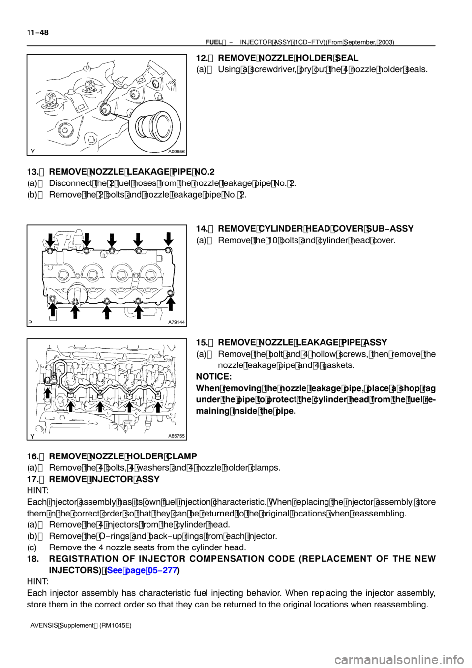
12. REMOVE NOZZLE HOLDER SEAL
(a) Using a screwdriver, pry out the 4 nozzle holder seals.
13. REMOVE NOZZLE LEAKAGE PIPE NO.2
(a) Disconnect the 2 fuel hoses from the nozzle leakage pipe No. 2.
(b) Remove the 2 bolts and nozzle leakage pipe No. 2. 14. REMOVE CYLINDER HEAD COVER SUB −ASSY
(a) Remove the 10 bolts and cylinder head cover.
15. REMOVE NOZZLE LEAKAGE PIPE ASSY
(a) Remove the bolt and 4 hollow screws, then remove the nozzle leakage pipe and 4 gaskets.
NOTICE:
When removing the nozzle leakage pipe, place a shop rag
under the pipe to protect the cylinder head from the fuel re-
maining inside the pipe.
16. REMOVE NOZZLE HOLDER CLAMP
(a) Remove the 4 bolts, 4 washers and 4 nozzle holder clamps.
17. REMOVE INJECTOR ASSY
HINT:
Each injector assembly has its own fuel injection characteristic. When replacing the injector assembly, store
them in the correct order so that they can be returned to the original locations when reassembling.
(a) Remove the 4 injectors from the cylinder head.
(b) Remove the O −rings and back −up rings from each injector.
(c) Remove the 4 nozzle seats from the cylinder head.
18. REGISTRATION OF INJECTOR COMPENSATION CODE (REPLACEMENT OF THE NEW INJECTORS) (See page 05 −277)
HINT:
Each injector assembly has characteristic fuel injecting behavior. When replacing the injector assembly,
store them in the correct order so that they can be returned to the original locations when reassembling.
Page 4578 of 5135
A79187
O−ring Back−up Ring
A92435
A85760
90_
− FUELINJECTOR ASSY (1CD−FTV)(From September, 2003)
11−49
AVENSIS Supplement (RM1045E)
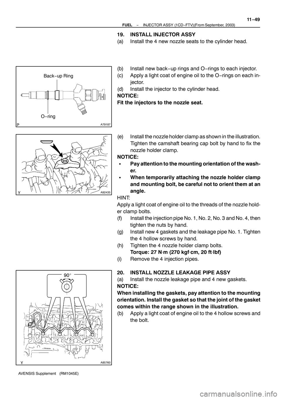
19. INSTALL INJECTOR ASSY
(a) Install the 4 new nozzle seats to the cylinder head.
(b) Install new back−up rings and O−rings to each injector.
(c) Apply a light coat of engine oil to the O−rings on each in-
jector.
(d) Install the injector to the cylinder head.
NOTICE:
Fit the injectors to the nozzle seat.
(e) Install the nozzle holder clamp as shown in the illustration.
Tighten the camshaft bearing cap bolt by hand to fix the
nozzle holder clamp.
NOTICE:
SPay attention to the mounting orientation of the wash-
er.
SWhen temporarily attaching the nozzle holder clamp
and mounting bolt, be careful not to orient them at an
angle.
HINT:
Apply a light coat of engine oil to the threads of the nozzle hold-
er clamp bolts.
(f) Install the injection pipe No. 1, No. 2, No. 3 and No. 4, then
tighten the nuts by hand.
(g) Install new 4 gaskets and the leakage pipe No. 1. Tighten
the 4 hollow screws by hand.
(h) Tighten the 4 nozzle holder clamp bolts.
Torque: 27 N�m (270 kgf�cm, 20 ft�lbf)
(i) Remove the 4 injection pipes.
20. INSTALL NOZZLE LEAKAGE PIPE ASSY
(a) Install the nozzle leakage pipe and 4 new gaskets.
NOTICE:
When installing the gaskets, pay attention to the mounting
orientation. Install the gasket so that the joint of the gasket
comes within the range shown in the illustration.
(b) Apply a light coat of engine oil to the 4 hollow screws and
the bolt.
Page 5130 of 5135
A64820
A01038
Seal Packing
A64968
793
481062
15
A65715
Paint Mark90� Engine
Front
14–74
– ENGINE MECHANICALCYLINDER BLOCK ASSY (1ZZ–FE/3ZZ–FE)
1ZZ–FE,3ZZ–FE ENGINE REPAIR MANUAL
(RM1099E)
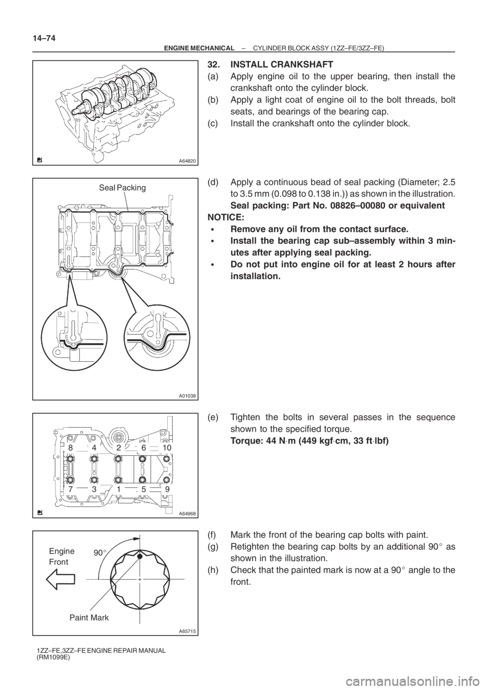
32. INSTALL CRANKSHAFT
(a) Apply engine oil to the upper bearing, then install the
crankshaft onto the cylinder block.
(b) Apply a light coat of engine oil to the bolt threads, bolt
seats, and bearings of the bearing cap.
(c) Install the crankshaft onto the cylinder block.
(d) Apply a continuous bead of seal packing (Diameter; 2.5
to 3.5 mm (0.098 to 0.138 in.)) as shown in the illustration.
Seal packing: Part No. 08826–00080 or equivalent
NOTICE:
�Remove any oil from the contact surface.
�Install the bearing cap sub–assembly within 3 min-
utes after applying seal packing.
�Do not put into engine oil for at least 2 hours after
installation.
(e) Tighten the bolts in several passes in the sequence
shown to the specified torque.
Torque: 44 N⋅m (449 kgf⋅cm, 33 ft⋅lbf)
(f) Mark the front of the bearing cap bolts with paint.
(g) Retighten the bearing cap bolts by an additional 90� as
shown in the illustration.
(h) Check that the painted mark is now at a 90� angle to the
front.
Page:
< prev 1-8 9-16 17-24