Page 3543 of 5135
C67634
C67635
D30541
D30542
D30543
± MANUAL TRANSMISSION/TRANSAXLEMANUAL TRANSAXLE ASSY (C250)
41±11
C250 M/T REPAIR MANUAL (RM1020E)
29. REMOVE SHIFT DETENT BALL
(a) Using a hexagon wrench, remove the 2 shift detent ball
plugs from the manual transmission case.
(b) Using a magnetic finger, remove the 2 seats, springs and
balls from the manual transmission case.
(c) Using a hexagon wrench, remove the shift detent ball
plug from the front transaxle case.
(d) Using a magnetic finger, remove the seat, spring and ball
from the front transaxle case.
30. REMOVE LOCK BALL ASSY NO.2
(a) Using a hexagon wrench, remove the lock ball assy No.2
from the manual transmission case.
Page 3728 of 5135
A57490
Cylinder Block Side
Intake Manifold Side
Exhaust Manifold Side
A13365
EM0183A57491
Width
± ENGINE MECHANICALCYLINDER HEAD ASSY (1AZ±FE)
14±31
1AZ±FE ENGINE REPAIR MANUAL (RM865E)
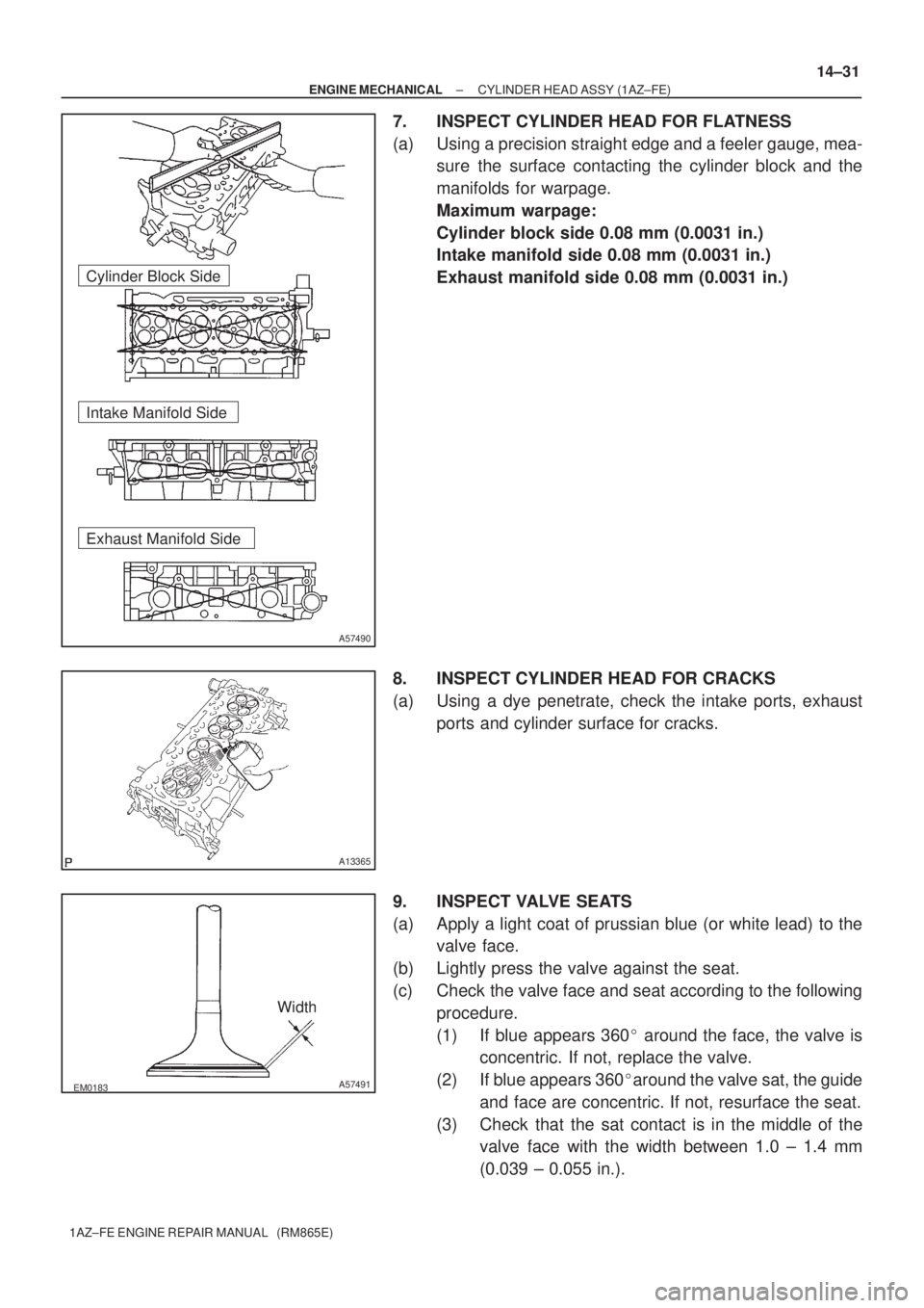
7. INSPECT CYLINDER HEAD FOR FLATNESS
(a) Using a precision straight edge and a feeler gauge, mea-
sure the surface contacting the cylinder block and the
manifolds for warpage.
Maximum warpage:
Cylinder block side 0.08 mm (0.0031 in.)
Intake manifold side 0.08 mm (0.0031 in.)
Exhaust manifold side 0.08 mm (0.0031 in.)
8. INSPECT CYLINDER HEAD FOR CRACKS
(a) Using a dye penetrate, check the intake ports, exhaust
ports and cylinder surface for cracks.
9. INSPECT VALVE SEATS
(a) Apply a light coat of prussian blue (or white lead) to the
valve face.
(b) Lightly press the valve against the seat.
(c) Check the valve face and seat according to the following
procedure.
(1) If blue appears 360� around the face, the valve is
concentric. If not, replace the valve.
(2) If blue appears 360�around the valve sat, the guide
and face are concentric. If not, resurface the seat.
(3) Check that the sat contact is in the middle of the
valve face with the width between 1.0 ± 1.4 mm
(0.039 ± 0.055 in.).
Page 3729 of 5135
1.0±1.4mm
45�
30�
A53031
1.0±1.4mm
75�
45�
A53032
A36626
A36627
14±32
± ENGINE MECHANICALCYLINDER HEAD ASSY (1AZ±FE)
1AZ±FE ENGINE REPAIR MANUAL (RM865E)
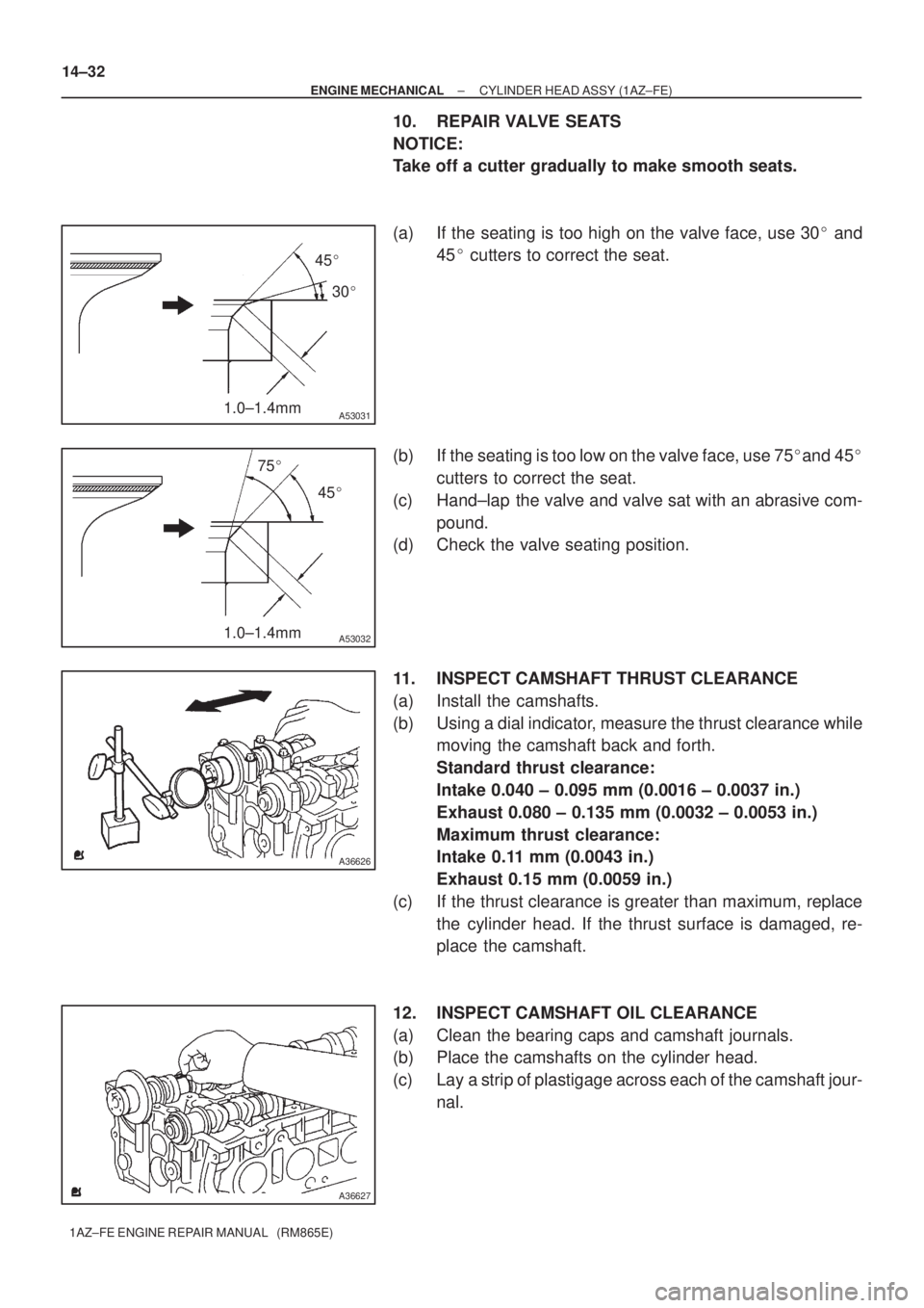
10. REPAIR VALVE SEATS
NOTICE:
Take off a cutter gradually to make smooth seats.
(a) If the seating is too high on the valve face, use 30� and
45� cutters to correct the seat.
(b) If the seating is too low on the valve face, use 75�and 45�
cutters to correct the seat.
(c) Hand±lap the valve and valve sat with an abrasive com-
pound.
(d) Check the valve seating position.
11. INSPECT CAMSHAFT THRUST CLEARANCE
(a) Install the camshafts.
(b) Using a dial indicator, measure the thrust clearance while
moving the camshaft back and forth.
Standard thrust clearance:
Intake 0.040 ± 0.095 mm (0.0016 ± 0.0037 in.)
Exhaust 0.080 ± 0.135 mm (0.0032 ± 0.0053 in.)
Maximum thrust clearance:
Intake 0.11 mm (0.0043 in.)
Exhaust 0.15 mm (0.0059 in.)
(c) If the thrust clearance is greater than maximum, replace
the cylinder head. If the thrust surface is damaged, re-
place the camshaft.
12. INSPECT CAMSHAFT OIL CLEARANCE
(a) Clean the bearing caps and camshaft journals.
(b) Place the camshafts on the cylinder head.
(c) Lay a strip of plastigage across each of the camshaft jour-
nal.
Page 3771 of 5135
140KN±01
A62780
SST
A62781
SST
14±28
± ENGINE MECHANICALCYLINDER HEAD ASSY (1ZZ±FE/3ZZ±FE)
1ZZ±FE,3ZZ±FE ENGINE REPAIR MANUAL
(RM923E)
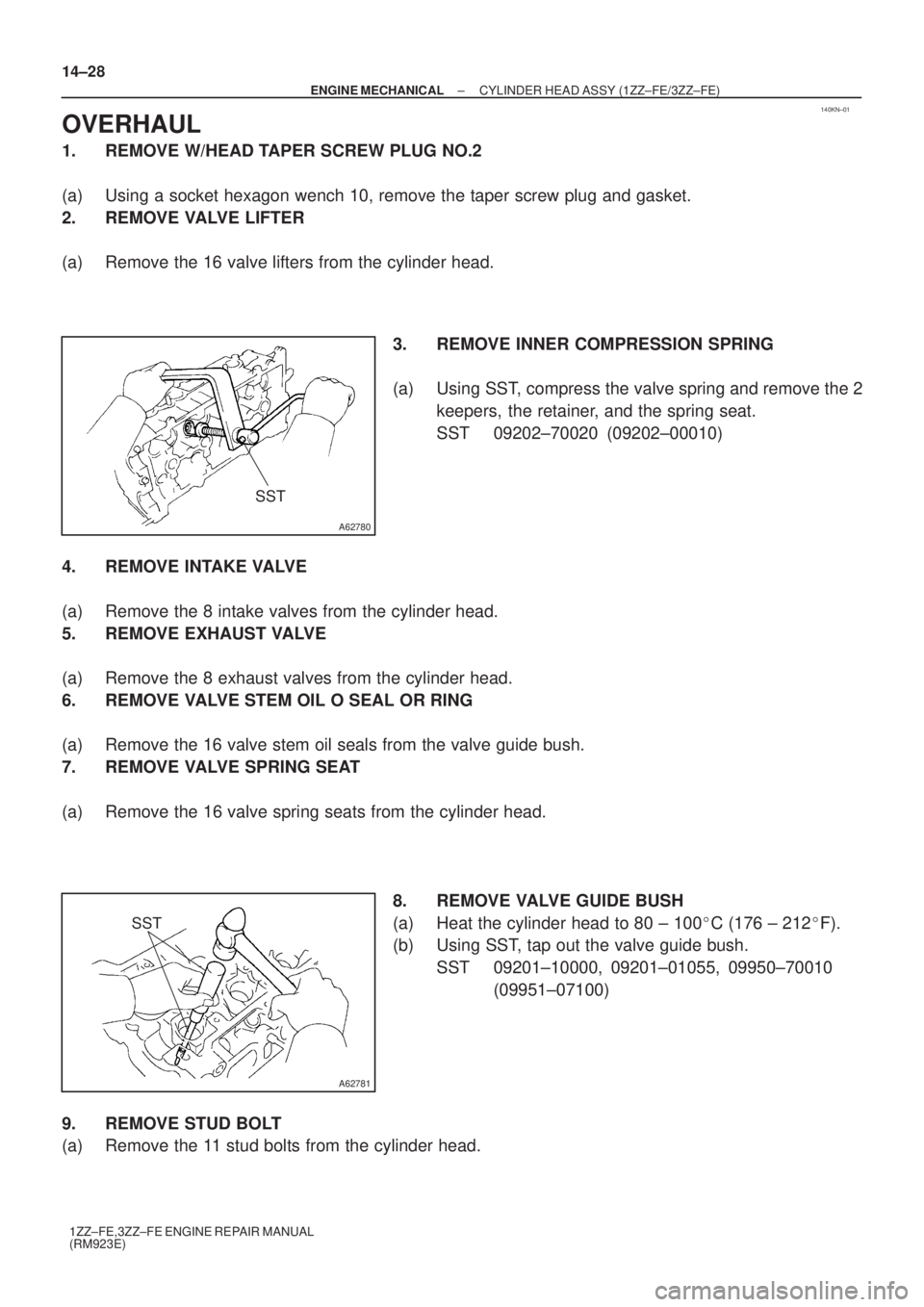
OVERHAUL
1. REMOVE W/HEAD TAPER SCREW PLUG NO.2
(a) Using a socket hexagon wench 10, remove the taper screw plug and gasket.
2. REMOVE VALVE LIFTER
(a) Remove the 16 valve lifters from the cylinder head.
3. REMOVE INNER COMPRESSION SPRING
(a) Using SST, compress the valve spring and remove the 2
keepers, the retainer, and the spring seat.
SST 09202±70020 (09202±00010)
4. REMOVE INTAKE VALVE
(a) Remove the 8 intake valves from the cylinder head.
5. REMOVE EXHAUST VALVE
(a) Remove the 8 exhaust valves from the cylinder head.
6. REMOVE VALVE STEM OIL O SEAL OR RING
(a) Remove the 16 valve stem oil seals from the valve guide bush.
7. REMOVE VALVE SPRING SEAT
(a) Remove the 16 valve spring seats from the cylinder head.
8. REMOVE VALVE GUIDE BUSH
(a) Heat the cylinder head to 80 ± 100�C (176 ± 212�F).
(b) Using SST, tap out the valve guide bush.
SST 09201±10000, 09201±01055, 09950±70010
(09951±07100)
9. REMOVE STUD BOLT
(a) Remove the 11 stud bolts from the cylinder head.
Page 3774 of 5135
EM2534
A62785
Margin
Thickness
EM2534
A62785
Margin
Thickness
A62786
Width
± ENGINE MECHANICALCYLINDER HEAD ASSY (1ZZ±FE/3ZZ±FE)
14±31
1ZZ±FE,3ZZ±FE ENGINE REPAIR MANUAL
(RM923E)
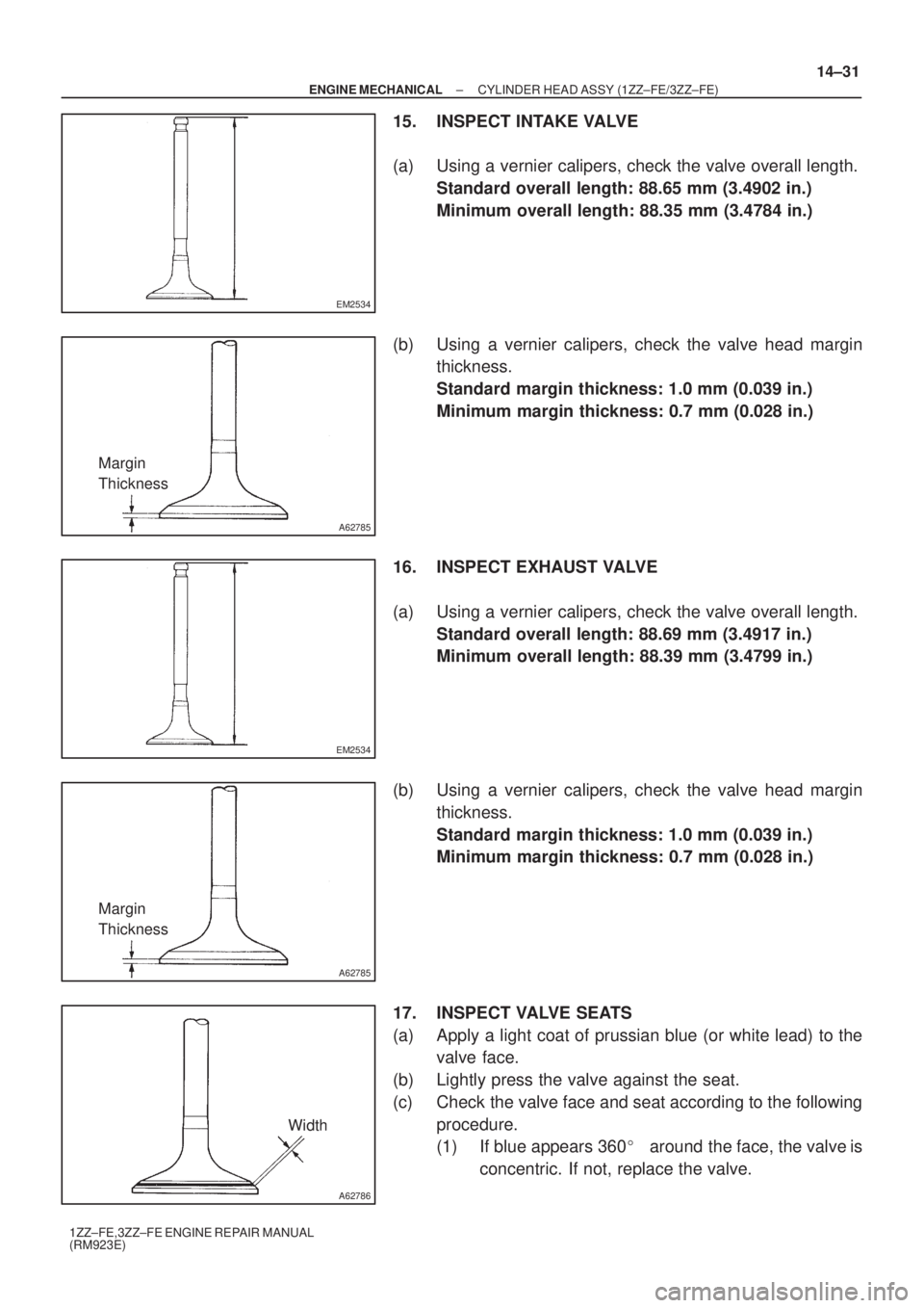
15. INSPECT INTAKE VALVE
(a) Using a vernier calipers, check the valve overall length.
Standard overall length: 88.65 mm (3.4902 in.)
Minimum overall length: 88.35 mm (3.4784 in.)
(b) Using a vernier calipers, check the valve head margin
thickness.
Standard margin thickness: 1.0 mm (0.039 in.)
Minimum margin thickness: 0.7 mm (0.028 in.)
16. INSPECT EXHAUST VALVE
(a) Using a vernier calipers, check the valve overall length.
Standard overall length: 88.69 mm (3.4917 in.)
Minimum overall length: 88.39 mm (3.4799 in.)
(b) Using a vernier calipers, check the valve head margin
thickness.
Standard margin thickness: 1.0 mm (0.039 in.)
Minimum margin thickness: 0.7 mm (0.028 in.)
17. INSPECT VALVE SEATS
(a) Apply a light coat of prussian blue (or white lead) to the
valve face.
(b) Lightly press the valve against the seat.
(c) Check the valve face and seat according to the following
procedure.
(1) If blue appears 360�around the face, the valve is
concentric. If not, replace the valve.
Page 3775 of 5135
A62787
1.0 ± 1.4 mm30� 45�
A62788
1.0 ± 1.4 mm60�
45�
P16860
A01080
14±32
± ENGINE MECHANICALCYLINDER HEAD ASSY (1ZZ±FE/3ZZ±FE)
1ZZ±FE,3ZZ±FE ENGINE REPAIR MANUAL
(RM923E)
(2) If blue appears 360� around the valve seat, the
guide and face are concentric. If not, resurface the
seat.
(3) Check that the seat contact is in the middle of the
valve face with the width between 1.0 ± 1.4 mm
(0.039 ± 0.055 in.).
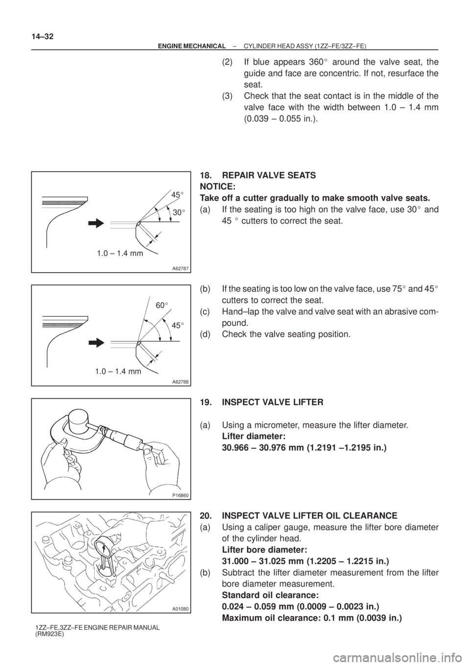
18. REPAIR VALVE SEATS
NOTICE:
Take off a cutter gradually to make smooth valve seats.
(a) If the seating is too high on the valve face, use 30� and
45 � cutters to correct the seat.
(b) If the seating is too low on the valve face, use 75� and 45�
cutters to correct the seat.
(c) Hand±lap the valve and valve seat with an abrasive com-
pound.
(d) Check the valve seating position.
19. INSPECT VALVE LIFTER
(a) Using a micrometer, measure the lifter diameter.
Lifter diameter:
30.966 ± 30.976 mm (1.2191 ±1.2195 in.)
20. INSPECT VALVE LIFTER OIL CLEARANCE
(a) Using a caliper gauge, measure the lifter bore diameter
of the cylinder head.
Lifter bore diameter:
31.000 ± 31.025 mm (1.2205 ± 1.2215 in.)
(b) Subtract the lifter diameter measurement from the lifter
bore diameter measurement.
Standard oil clearance:
0.024 ± 0.059 mm (0.0009 ± 0.0023 in.)
Maximum oil clearance: 0.1 mm (0.0039 in.)
Page 3828 of 5135
140DR±03
A56671
SST
A62594
SST
A09561
A09676
± ENGINE MECHANICALCYLINDER HEAD ASSY (1CD±FTV)
14±23
1CD±FTV ENGINE REPAIR MANUAL (RM927E)
OVERHAUL
1. REMOVE VALVE LIFTER
HINT:
Arrange the valve lifters in the correct order.
2. REMOVE INTAKE VALVE
(a) Using SST, compress the valve spring and remove the 2
keepers.
SST 09202±70020 (09202±00010)
(b) Remove the spring retainer, valve spring and valve.
3. REMOVE EXHAUST VALVE
(a) Using SST, compress the valve spring and remove the 2
keepers.
SST 09202±70020 (09202±00010)
(b) Remove the spring retainer, valve spring and valve.
4. REMOVE VALVE STEM OIL O SEAL OR RING
(a) Using needle±nose pliers, remove the oil seal.
5. REMOVE VALVE SPRING SEAT PLATE WASHER
(a) Using compressed air and a magnetic finger, remove the
spring seat by blowing air.
HINT:
Arrange the valves, valve springs, spring seats and spring re-
tainers in the correct order.
Page 3834 of 5135
A56676
A56677
SST
A56678
Sharp 6 mm
Reamer
± ENGINE MECHANICALCYLINDER HEAD ASSY (1CD±FTV)
14±29
1CD±FTV ENGINE REPAIR MANUAL (RM927E)
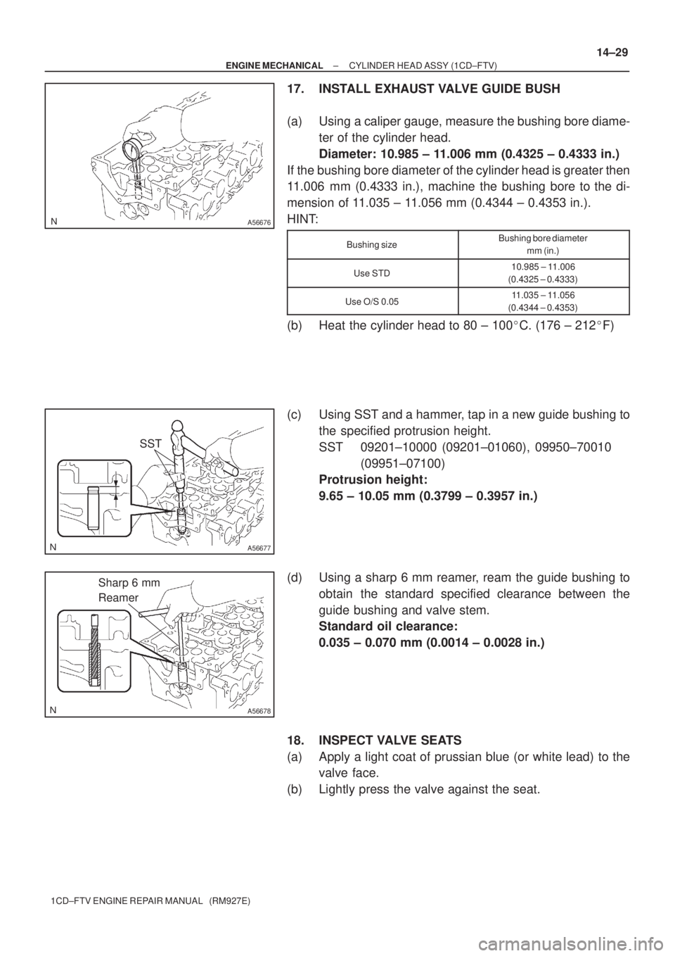
17. INSTALL EXHAUST VALVE GUIDE BUSH
(a) Using a caliper gauge, measure the bushing bore diame-
ter of the cylinder head.
Diameter: 10.985 ± 11.006 mm (0.4325 ± 0.4333 in.)
If the bushing bore diameter of the cylinder head is greater then
11.006 mm (0.4333 in.), machine the bushing bore to the di-
mension of 11.035 ± 11.056 mm (0.4344 ± 0.4353 in.).
HINT:
Bushing sizeBushing bore diameter
mm (in.)
Use STD10.985 ± 11.006
(0.4325 ± 0.4333)
Use O/S 0.0511.035 ± 11.056
(0.4344 ± 0.4353)
(b) Heat the cylinder head to 80 ± 100�C. (176 ± 212�F)
(c) Using SST and a hammer, tap in a new guide bushing to
the specified protrusion height.
SST 09201±10000 (09201±01060), 09950±70010
(09951±07100)
Protrusion height:
9.65 ± 10.05 mm (0.3799 ± 0.3957 in.)
(d) Using a sharp 6 mm reamer, ream the guide bushing to
obtain the standard specified clearance between the
guide bushing and valve stem.
Standard oil clearance:
0.035 ± 0.070 mm (0.0014 ± 0.0028 in.)
18. INSPECT VALVE SEATS
(a) Apply a light coat of prussian blue (or white lead) to the
valve face.
(b) Lightly press the valve against the seat.