Page 3934 of 5135

05±420
± DIAGNOSTICSSFI SYSTEM (1AZ±FSE)
AVENSIS REPAIR MANUAL (RM1018E)
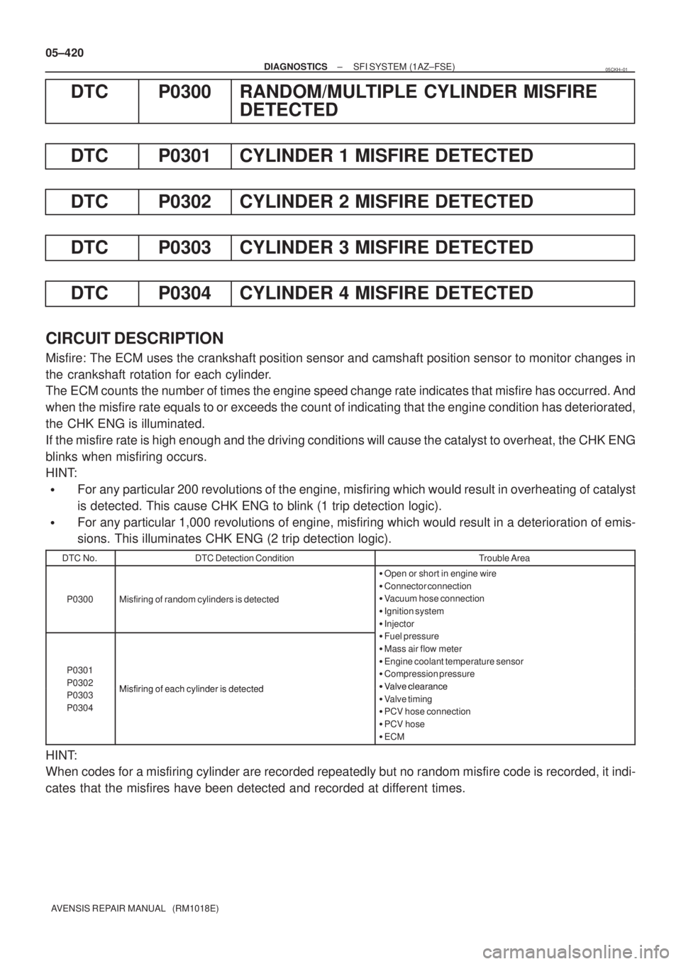
DTC P0300 RANDOM/MULTIPLE CYLINDER MISFIRE
DETECTED
DTC P0301 CYLINDER 1 MISFIRE DETECTED
DTC P0302 CYLINDER 2 MISFIRE DETECTED
DTC P0303 CYLINDER 3 MISFIRE DETECTED
DTC P0304 CYLINDER 4 MISFIRE DETECTED
CIRCUIT DESCRIPTION
Misfire: The ECM uses the crankshaft position sensor and camshaft position sensor to monitor changes in
the crankshaft rotation for each cylinder.
The ECM counts the number of times the engine speed change rate indicates that misfire has occurred. And
when the misfire rate equals to or exceeds the count of indicating that the engine condition has deteriorated,
the CHK ENG is illuminated.
If the misfire rate is high enough and the driving conditions will cause the catalyst to overheat, the CHK ENG
blinks when misfiring occurs.
HINT:
�For any particular 200 revolutions of the engine, misfiring which would result in overheating of catalyst
is detected. This cause CHK ENG to blink (1 trip detection logic).
�For any particular 1,000 revolutions of engine, misfiring which would result in a deterioration of emis-
sions. This illuminates CHK ENG (2 trip detection logic).
DTC No.DTC Detection ConditionTrouble Area
P0300Misfiring of random cylinders is detected
�Open or short in engine wire
�Connector connection
�Vacuum hose connection
�Ignition system
�Injector
P0301
P0302
Misfiring of each cylinder is detected
�Fuel pressure
�Mass air flow meter
�Engine coolant temperature sensor
�Compression pressure
�
Valve clearanceP0302
P0303
P0304Misfiring of each cylinder is detected�Valve clearance
�Valve timing
�PCV hose connection
�PCV hose
�ECM
HINT:
When codes for a misfiring cylinder are recorded repeatedly but no random misfire code is recorded, it indi-
cates that the misfires have been detected and recorded at different times.
05CKH±01
Page 4207 of 5135

05−146
− DIAGNOSTICSSFI SYSTEM (2AZ−FSE)
AVENSIS Supplement (RM1045E)
DTC P0300 RANDOM/MULTIPLE CYLINDER MISFIRE
DETECTED
DTC P0301CYLINDER1MISFIRE DETECTED
DTC P0302 CYLINDER 2 MISFIRE DETECTED
DTC P0303 CYLINDER 3 MISFIRE DETECTED
DTC P0304 CYLINDER 4 MISFIRE DETECTED
CIRCUIT DESCRIPTION
When a misfire occurs in the engine, hydrocarbons (HC) enter the exhaust in high concentrations. If this HC
concentration is high enough, there could be an increase in exhaust emissions levels. High concentrations
of HC can also cause to temperature of the catalyst to increase, possibly damaging the catalyst. To prevent
this increase in emissions and limit the possibility of thermal damage, the ECM monitors the misfire rate.
When the temperature of the catalyst reaches a point of thermal degradation, the ECM will blink the CHK
ENG. For monitoring misfire, the ECM uses both the camshaft position sensor and the crankshaft position
sensor. The camshaft position sensor is used to identify misfiring cylinders and the crankshaft position sen-
sor is used to measure variations in the crankshaft rotation speed. The misfire counter increments when
crankshaft rotation speed variations exceed threshold values.
If the misfiring rate exceeds the threshold value and could cause emissions deterioration, the ECM illumi-
nates the CHK ENG.
HINT:
SFor any particular 200 revolutions of the engine, misfiring which would result in overheating of catalyst
is detected. This cause CHK ENG to blink (1trip detection logic).
SFor any particular1,000 revolutions of the engine, misfiring which would result in a deterioration of
emissions is detected. This illuminates CHK ENG (2 trip detection logic).
05HII−01
Page 4292 of 5135

B62793
Reference:
A/F Sensor A/F Sensor
Heater Relay
Heater
Sensor
AF2+ HAF2
Duty
Control ECM
From
Battery
A/F Fuse
AF2−
MREL 05−306
− DIAGNOSTICSECD SYSTEM (1CD−FTV)(From September, 2003)
AVENSIS Supplement (RM1045E)
HINT:
The ECM provides a pulse width modulated control circuit to adjust current through the heater. The A/F sen-
sor heater circuit uses a relay on the B+ side of the circuit.
DTC No.DTC Detection ConditionTrouble Area
P0031Heated current is 1.5 A or less when the heater operates
(1 trip detection logic)
SOpen in A/F sensor heater circuit
SA/F sensor heater
SA/F sensor heater relay
SECM
MONITOR DESCRIPTION
The inner surface of the A/F sensor element is exposed to outside air. The outer surface of the sensor ele-
ment is exposed to exhaust gases. The sensor element is made of platinum coated zirconia and includes
an integrated heating element. The zirconia element generates small voltage when there is a large differ-
ence in the oxygen concentrations of the exhaust and the outside air. The platinum coating amplifies the
voltage generation. When heated, the sensor becomes very efficient. If the temperature of the exhaust is
low, the sensor will not generate useful voltage signals without supplemental heating. The ECM regulates
the supplemental heating using a duty−cycle approach to regulate the average current in the heater ele-
ment. If the heater current is out of the normal range, the sensor’s output signals will be inaccurate and the
ECM can not regulate the air−fuel ratio properly. When the heater current is out of the normal operating
range, the ECM interprets this as a malfunction and sets a DTC.
Page 4745 of 5135
190JF−03
4
1
23
A34838
− STARTING & CHARGINGPRE−HEATING SYSTEM (1CD−FTV)(From September,
2003)19−13
AVENSIS Supplement (RM1045E)
INSPECTION
1. INSPECT GLOW PLUG RELAY ASSY
(a) Using an ohmmeter, measure the resistance between the
terminals.
Specified condition:
Tester ConnectionSpecified Condition
1−210 k�or Higher
1−2
Below 1�
(When battery voltage is applied to
terminals 3 and 4 )
If the result is not as specified, replace the glow plug relay.
Page 4976 of 5135

05–118
– DIAGNOSTICSSFI SYSTEM (1ZZ–FE/3ZZ–FE)(From February, 2004)
AVENSIS REPAIR MANUAL SUPPLEMENT
(RM1098E)
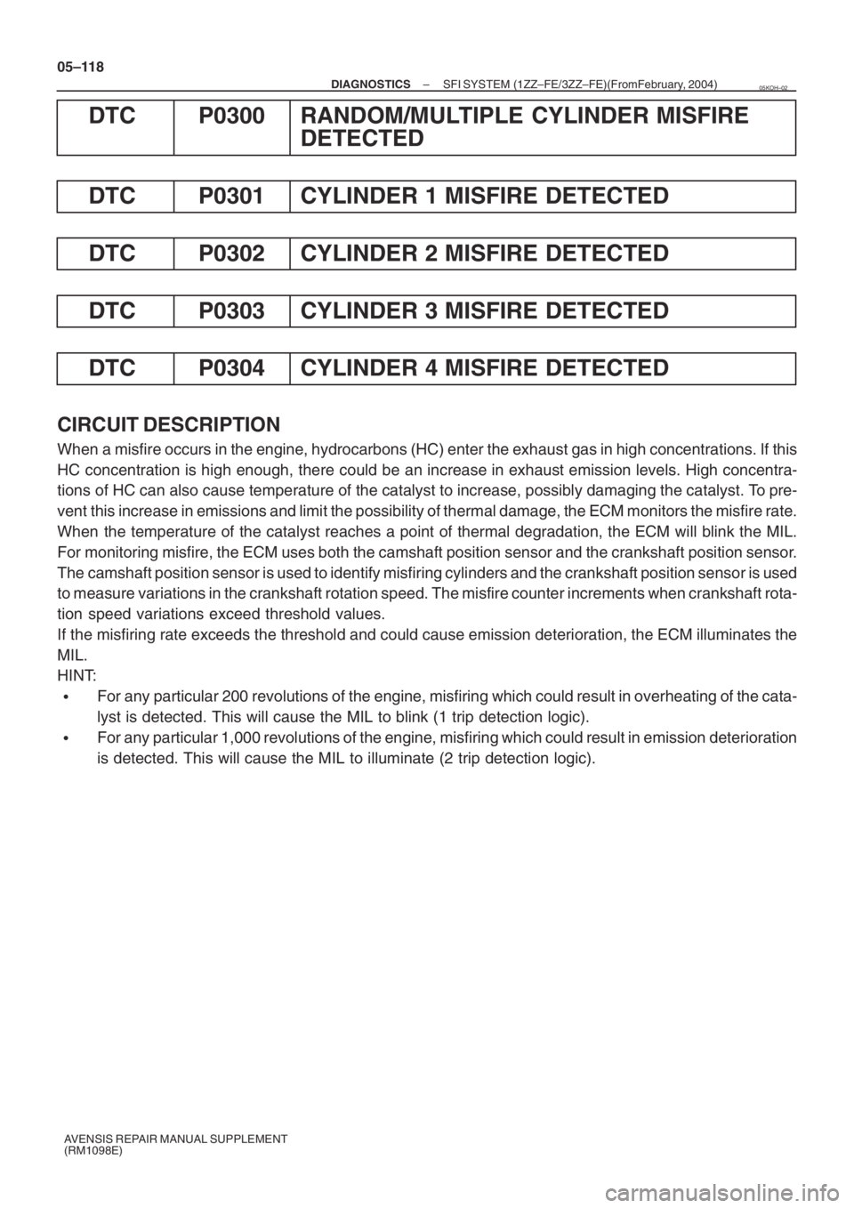
DTC P0300 RANDOM/MULTIPLE CYLINDER MISFIRE
DETECTED
DTC P0301 CYLINDER 1 MISFIRE DETECTED
DTC P0302 CYLINDER 2 MISFIRE DETECTED
DTC P0303 CYLINDER 3 MISFIRE DETECTED
DTC P0304 CYLINDER 4 MISFIRE DETECTED
CIRCUIT DESCRIPTION
When a misfire occurs in the engine, hydrocarbons (HC) enter the exhaust gas in high concentrations. If this
HC concentration is high enough, there could be an increase in exhaust emission levels. High concentra-
tions of HC can also cause temperature of the catalyst to increase, possibly damaging the catalyst. To pre-
vent this increase in emissions and limit the possibility of thermal damage, the ECM monitors the misfire rate.
When the temperature of the catalyst reaches a point of thermal degradation, the ECM will blink the MIL.
For monitoring misfire, the ECM uses both the camshaft position sensor and the crankshaft position sensor.
The camshaft position sensor is used to identify misfiring cylinders and the crankshaft position sensor is used
to measure variations in the crankshaft rotation speed. The misfire counter increments when crankshaft rota-
tion speed variations exceed threshold values.
If the misfiring rate exceeds the threshold and could cause emission deterioration, the ECM illuminates the
MIL.
HINT:
�For any particular 200 revolutions of the engine, misfiring which could result in overheating of the cata-
lyst is detected. This will cause the MIL to blink (1 trip detection logic).
�For any particular 1,000 revolutions of the engine, misfiring which could result in emission deterioration
is detected. This will cause the MIL to illuminate (2 trip detection logic).
05KOH–02
Page:
< prev 1-8 9-16 17-24