Page 1426 of 5135
05C4W±01
I30195
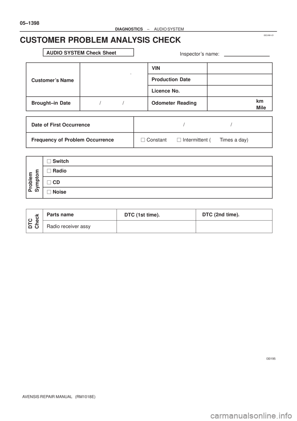
AUDIO SYSTEM Check Sheet
Inspector 's name:
Customer 's NameVIN
Production Date
Licence No.
Odometer Reading / /km
Mile
Frequency of Problem Occurrence / /
� Constant � Intermittent ( Times a day) Brought±in Date
Date of First Occurrence
Problem
Symptom
� Radio
Radio receiver assy
DTC
Check
Parts name
DTC (1st time).DTC (2nd time). � Switch
� Noise � CD 05±1398
± DIAGNOSTICSAUDIO SYSTEM
AVENSIS REPAIR MANUAL (RM1018E)
CUSTOMER PROBLEM ANALYSIS CHECK
Page 1427 of 5135
0549G±09
05±1396
±
DIAGNOSTIC SAUDIO SYSTEM
A VENSIS RE PAIR MANUAL (RM1018E)
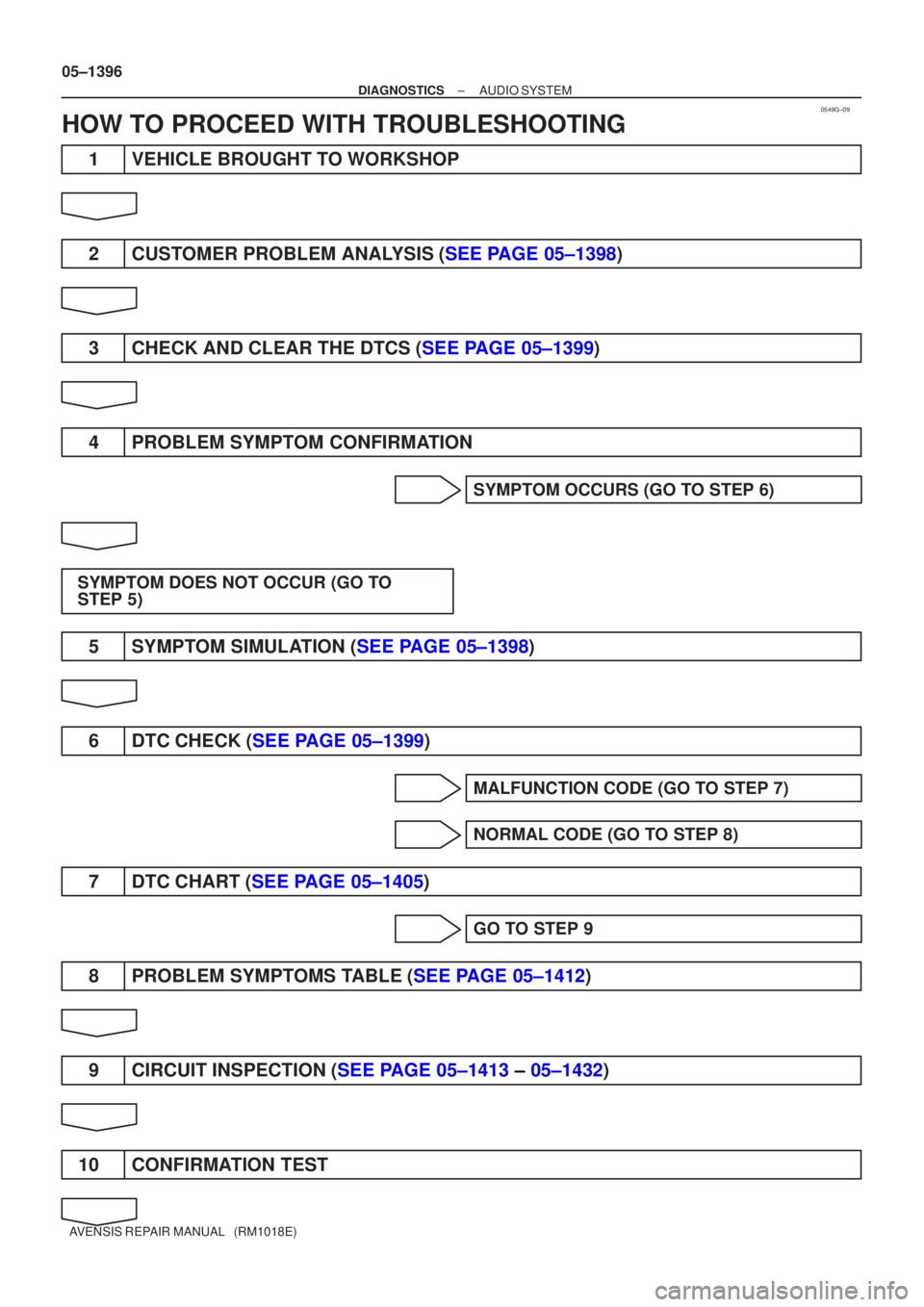
HOW T O PROCEED WITH TROUBLESHOOTING
1 VEHICL E BROUGHT TO WORKSHOP
2 CUSTOMER PROBLEM ANA LYSIS ( SEE P AGE 05±1398 )
3 CHECK AND CLEAR THE DTCS ( SEE PAGE 05±1399 )
4 PROBLEM SYMPTOM CONFIRMATION
SYMPTOM OCCURS (GO TO STEP 6)
SYMPTOM DOES NOT OCCUR (GO TO
STEP 5)
5 SYMP TOM SIMUL ATION ( SEE PAGE 05±1398 )
6 DTC CHECK ( SEE PAGE 05±1399 )
MALFUNCTION CODE (GO TO STEP 7)
NORMAL CODE (GO TO STEP 8)
7DTC CHART ( SEE PAGE 05±1405 )
GO TO STEP 9
8PROBLEM SYMP TOMS T ABLE ( SEE PAGE 05±1412 )
9 CIRCUIT INSPECTION ( SEE PAGE 05±1413 ± 05±1432 )
10 CONFIRMATION TEST
Page 1428 of 5135
± DIAGNOSTICSAUDIO SYSTEM
05±1397
AVENSIS REPAIR MANUAL (RM1018E)
END
Page 1429 of 5135
0549F±10
30 kHz 300 kHz 3 MHz 30 MHz 300 MHz
LF MF HF VHF
AM FM
Frequency modulation Frequency
Designation
Radio wave
Modulation Amplitude modulation
BE2818
FM (Stereo)
FM (Monaural)
AM
BE2819
FadingIonosphere
± DIAGNOSTICSAUDIO SYSTEM
05±1393
AVENSIS REPAIR MANUAL (RM1018E)
AUDIO SYSTEM
DESCRIPTION
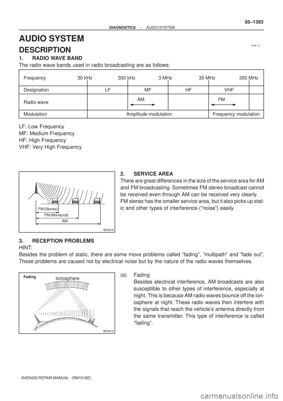
1. RADIO WAVE BAND
The radio wave bands used in radio broadcasting are as follows:
LF: Low Frequency
MF: Medium Frequency
HF: High Frequency
VHF: Very High Frequency
2. SERVICE AREA
There are great differences in the size of the service area for AM
and FM broadcasting. Sometimes FM stereo broadcast cannot
be received even through AM can be received very clearly.
FM stereo has the smaller service area, but it also picks up stat-
ic and other types of interference (ºnoiseº) easily.
3. RECEPTION PROBLEMS
HINT:
Besides the problem of static, there are some move problems called ºfadingº, ºmultipathº and ºfade outº.
These problems are caused not by electrical noise but by the nature of the radio waves themselves.
(a) Fading
Besides electrical interference, AM broadcasts are also
susceptible to other types of interference, especially at
night. This is because AM radio waves bounce off the ion-
osphere at night. These radio waves then interfere with
the signals that reach the vehicle's antenna directly from
the same transmitter. This type of interference is called
ºfadingº.
Page 1430 of 5135
BE2820
Multipath
BE2821
Fade Out 05±1394
± DIAGNOSTICSAUDIO SYSTEM
AVENSIS REPAIR MANUAL (RM1018E)
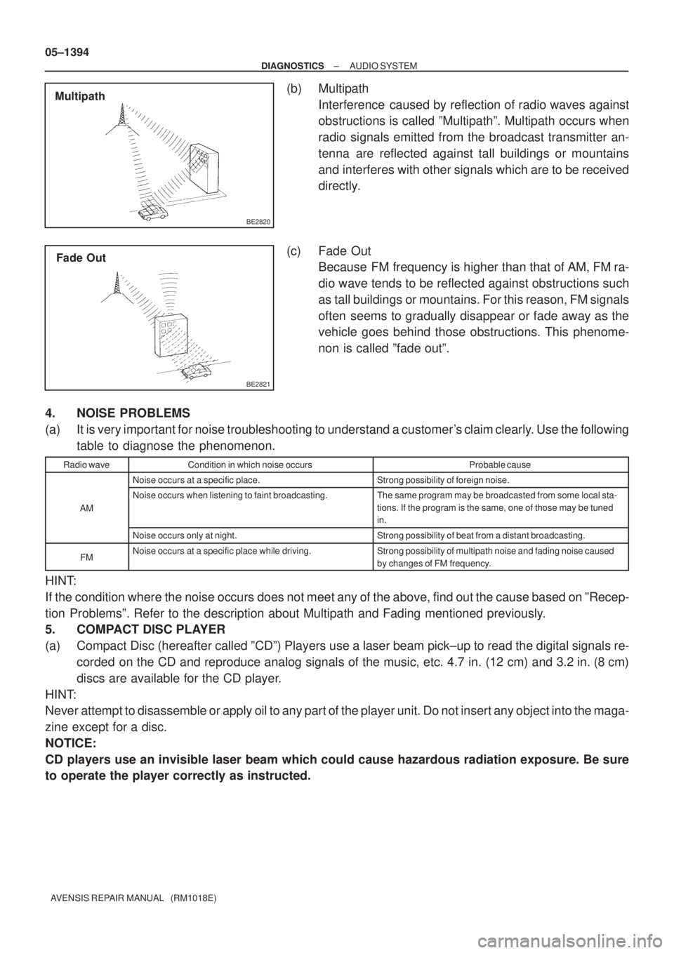
(b) Multipath
Interference caused by reflection of radio waves against
obstructions is called ºMultipathº. Multipath occurs when
radio signals emitted from the broadcast transmitter an-
tenna are reflected against tall buildings or mountains
and interferes with other signals which are to be received
directly.
(c) Fade Out
Because FM frequency is higher than that of AM, FM ra-
dio wave tends to be reflected against obstructions such
as tall buildings or mountains. For this reason, FM signals
often seems to gradually disappear or fade away as the
vehicle goes behind those obstructions. This phenome-
non is called ºfade outº.
4. NOISE PROBLEMS
(a) It is very important for noise troubleshooting to understand a customer's claim clearly. Use the following
table to diagnose the phenomenon.
Radio waveCondition in which noise occursProbable cause
Noise occurs at a specific place.Strong possibility of foreign noise.
AM
Noise occurs when listening to faint broadcasting.The same program may be broadcasted from some local sta-
tions. If the program is the same, one of those may be tuned
in.
Noise occurs only at night.Strong possibility of beat from a distant broadcasting.
FMNoise occurs at a specific place while driving.Strong possibility of multipath noise and fading noise caused
by changes of FM frequency.
HINT:
If the condition where the noise occurs does not meet any of the above, find out the cause based on ºRecep-
tion Problemsº. Refer to the description about Multipath and Fading mentioned previously.
5. COMPACT DISC PLAYER
(a) Compact Disc (hereafter called ºCDº) Players use a laser beam pick±up to read the digital signals re-
corded on the CD and reproduce analog signals of the music, etc. 4.7 in. (12 cm) and 3.2 in. (8 cm)
discs are available for the CD player.
HINT:
Never attempt to disassemble or apply oil to any part of the player unit. Do not insert any object into the maga-
zine except for a disc.
NOTICE:
CD players use an invisible laser beam which could cause hazardous radiation exposure. Be sure
to operate the player correctly as instructed.
Page 1431 of 5135
N17398
Example :
HeadCapstan
Pinch Roller
BE4331
± DIAGNOSTICSAUDIO SYSTEM
05±1395
AVENSIS REPAIR MANUAL (RM1018E)
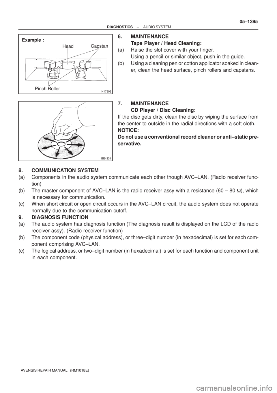
6. MAINTENANCE
Tape Player / Head Cleaning:
(a) Raise the slot cover with your finger.
Using a pencil or similar object, push in the guide.
(b) Using a cleaning pen or cotton applicator soaked in clean-
er, clean the head surface, pinch rollers and capstans.
7. MAINTENANCE
CD Player / Disc Cleaning:
If the disc gets dirty, clean the disc by wiping the surface from
the center to outside in the radial directions with a soft cloth.
NOTICE:
Do not use a conventional record cleaner or anti±static pre-
servative.
8. COMMUNICATION SYSTEM
(a) Components in the audio system communicate each other though AVC±LAN. (Radio receiver func-
tion)
(b) The master component of AVC±LAN is the radio receiver assy with a resistance (60 ± 80 �), which
is necessary for communication.
(c) When short circuit or open circuit occurs in the AVC±LAN circuit, the audio system does not operate
normally due to the communication cutoff.
9. DIAGNOSIS FUNCTION
(a) The audio system has diagnosis function (The diagnosis result is displayed on the LCD of the radio
receiver assy). (Radio receiver function)
(b) The component code (physical address), or three±digit number (in hexadecimal) is set for each com-
ponent comprising AVC±LAN.
(c) The logical address, or two±digit number (in hexadecimal) is set for each function and component unit
in each component.
Page 1460 of 5135
I35619
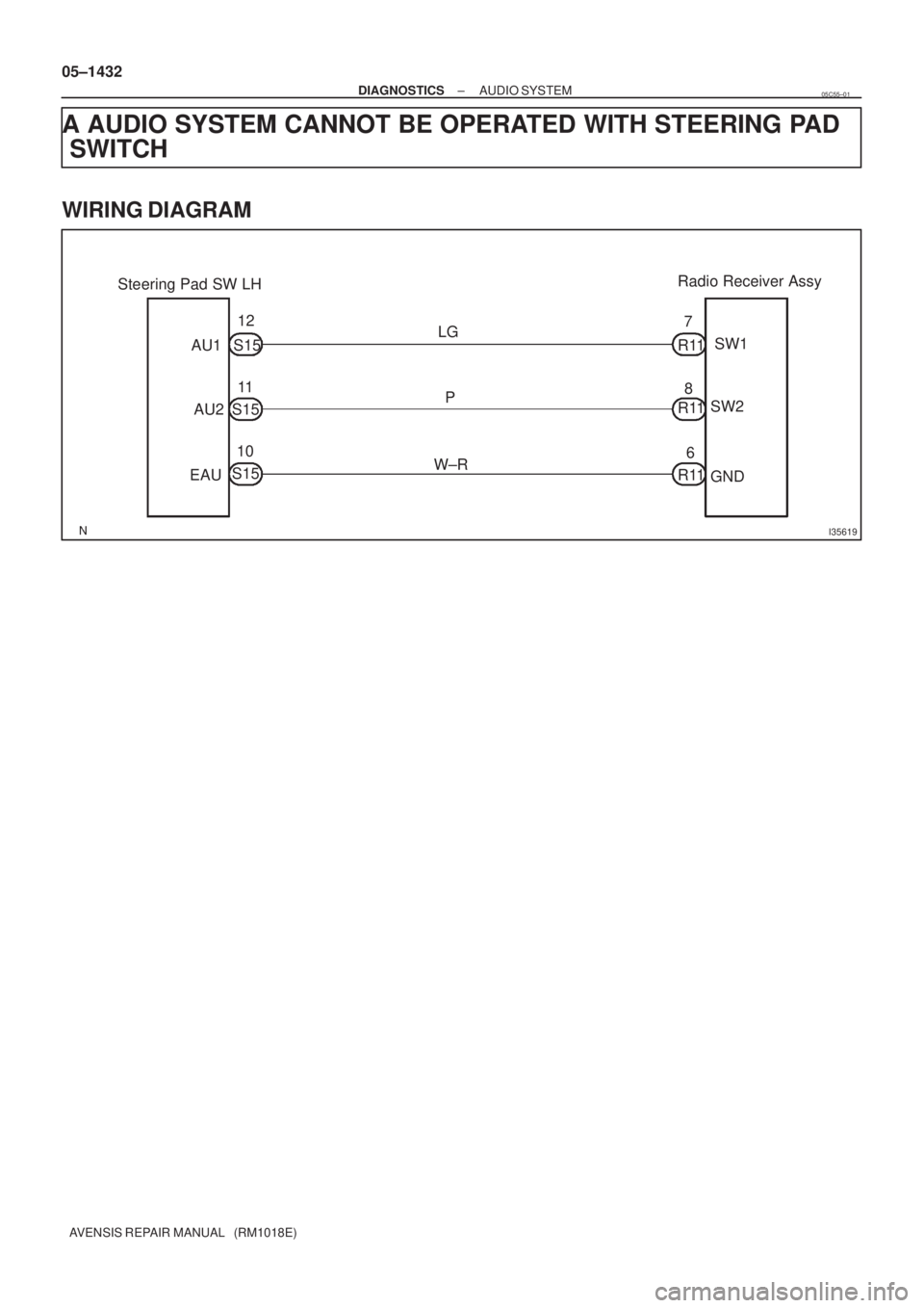
Steering Pad SW LH
AU1
AU2
EAU12
11
10LG
P
W±RR117
8
6SW1
SW2
GND Radio Receiver Assy
R11
R11 S15
S15
S15 05±1432
± DIAGNOSTICSAUDIO SYSTEM
AVENSIS REPAIR MANUAL (RM1018E)
A AUDIO SYSTEM CANNOT BE OPERATED WITH STEERING PAD
SWITCH
WIRING DIAGRAM
05C55±01
Page 1461 of 5135
I35662
AU1
AU2 EAU
± DIAGNOSTICSAUDIO SYSTEM
05±1433
AVENSIS REPAIR MANUAL (RM1018E)
INSPECTION PROCEDURE
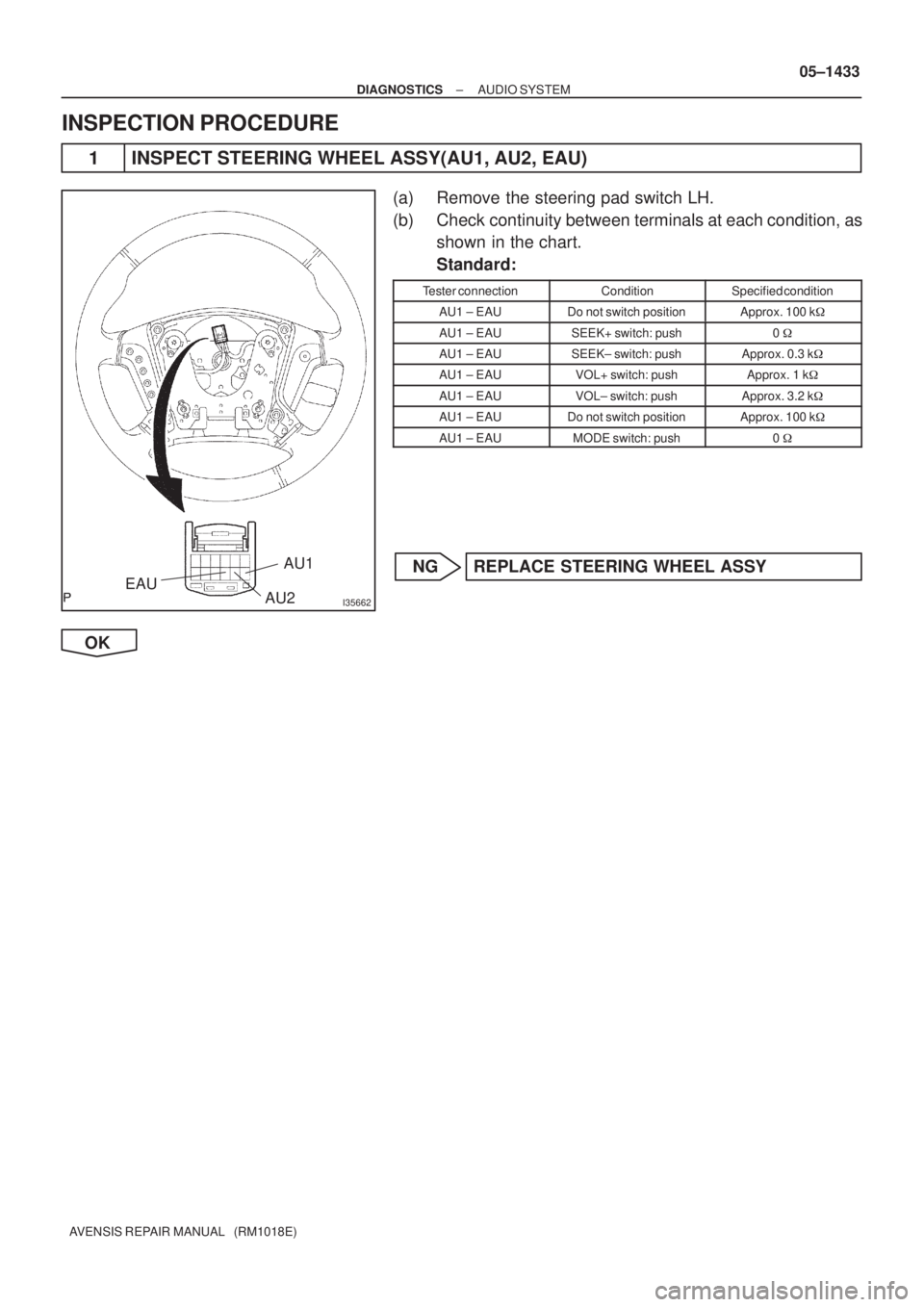
1 INSPECT STEERING WHEEL ASSY(AU1, AU2, EAU)
(a) Remove the steering pad switch LH.
(b) Check continuity between terminals at each condition, as
shown in the chart.
Standard:
Tester connectionConditionSpecified condition
AU1 ± EAUDo not switch positionApprox. 100 k�
AU1 ± EAUSEEK+ switch: push0 �
AU1 ± EAUSEEK± switch: pushApprox. 0.3 k�
AU1 ± EAUVOL+ switch: pushApprox. 1 k�
AU1 ± EAUVOL± switch: pushApprox. 3.2 k�
AU1 ± EAUDo not switch positionApprox. 100 k�
AU1 ± EAUMODE switch: push0 �
NG REPLACE STEERING WHEEL ASSY
OK