Page 3875 of 5135
±
DIAGNOSTICS SFI SYSTEM (1ZZ±FE/3ZZ±FE)
05±15
AVENSIS REPAIR MANUAL (RM1018E)
6CHECK FUEL PRESSURE (See page 11±5)
NGPROCEED TO PAGE 11±1 AND CONTINUE TO
TROUBLESHOOT
OK
7CHECK FOR SPARK (See page 18±1)
NGPROCEED TO PAGE 18±1 AND CONTINUE TO TROUBLESHOOT
OK
PROCEED TO PROBLEM SYMPTOMS TABLE ON PAGE 05±22
Page 3876 of 5135
05±44
±
DIAGNOSTICS SFI SYSTEM(1ZZ±FE/3ZZ±FE)
AVENSIS REPAIR MANUAL (RM1018E)
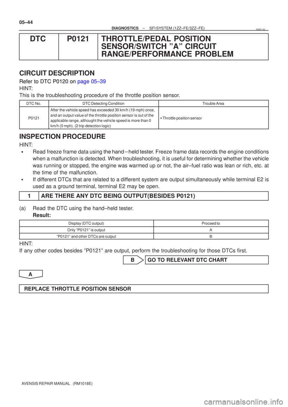
DTCP0121THROTTLE/PEDAL POSITION SENSOR/SWITCH ºAº CIRCUIT
RANGE/PERFORMANCE PROBLEM
CIRCUIT DESCRIPTION
Refer to DTC P0120 on page 05±39
HINT:
This is the troubleshooting procedure of the throttle position sensor.
DTC No.DTC Detecting ConditionTrouble Area
P0121
After the vehicle speed has exceeded 30 km/h (19 mph) once,
and an output value of the throttle position sensor is out of the
applicable range, althought the vehicle speed is more than 0
km/h (0 mph). (2 trip detection logic)
�Throttle position sensor
INSPECTION PROCEDURE
HINT:
�Read freeze frame data using \f�� �� ����\b� \f��\f�
� Freeze frame data records the engine conditions
when a malfunction is detected. When troubleshooting, it is useful for d\
etermining whether the vehicle
was running or stopped, the engine was warmed up or not, the air±fuel ra\
tio was lean or rich, etc. at
the time of the malfunction.
�If different DTCs that are related to a different system are output simultaneously while terminal E2 is
used as a ground terminal, terminal E2 may be open.
1 ARE THERE ANY DTC BEING OUTPUT(BESIDES P0121)
(a) Read the DTC using the hand±held tester.
Result:
Display (DTC output)Proceed to
Only ºP0121º is outputA
ºP0121º and other DTCs are outputB
HINT:
If any other codes besides ºP0121º are output, perform the troublesh\
ooting for those DTCs first.
B GO TO RELEVANT DTC CHART
A
REPLACE THROTTLE POSITION SENSOR
05B3T±02
Page 3877 of 5135
05±174
±
DIAGNOSTICS SFI SYSTEM(1AZ±FE)
AVENSIS REPAIR MANUAL (RM1018E)
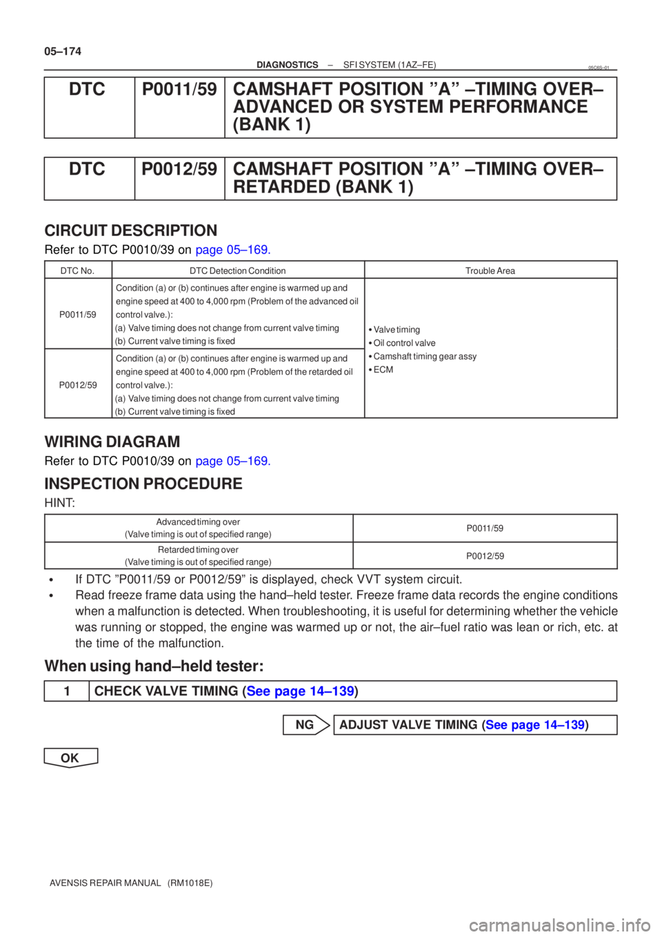
DTCP0011/59CAMSHAFT POSITION ºAº ±TIMING OVER± ADVANCED OR SYSTEM PERFORMANCE
(BANK 1)
DTCP0012/59CAMSHAFT POSITION ºAº ±TIMING OVER± RETARDED (BANK 1)
CIRCUIT DESCRIPTION
Refer to DTC P0010/39 on page 05±169.
DTC No.DTC Detection ConditionTrouble Area
P0011/59
Condition (a) or (b) continues after engine is warmed up and
engine speed at 400 to 4,000 rpm (Problem of the advanced oil
control valve.):
(a)Valve timing does not change from current valve timing
(b)Current valve timing is fixed
� Valve timing
� Oil control valve
P0012/59
Condition (a) or (b) continues after engine is warmed up and
engine speed at 400 to 4,000 rpm (Problem of the retarded oil
control valve.):
(a)Valve timing does not change from current valve timing
(b)Current valve timing is fixed
Oil control valve
� Camshaft timing gear assy
� ECM
WIRING DIAGRAM
Refer to DTC P0010/39 on page 05±169.
INSPECTION PROCEDURE
HINT:
Advanced timing over
(Valve timing is out of specified range)P0011/59
Retarded timing over
(Valve timing is out of specified range)P0012/59
�If DTC ºP0011/59 or P0012/59º is displayed, check VVT system circuit.
�Read freeze frame data using the hand±held tester. Freeze frame data records the engine conditions
when a malfunction is detected. When troubleshooting, it is useful for deter\
mining whether the vehicle
was running or stopped, the engine was warmed up or not, the air±fuel ra\
tio was lean or rich, etc. at
the time of the malfunction.
When using hand±held tester:
1CHECK VALVE TIMING (See page 14±139)
NGADJUST VALVE TIMING (See page 14±139)
OK
05C6S±01
Page 3878 of 5135
± DIAGNOSTICSSFI SYSTEM (1AZ±FE)
05±175
AVENSIS REPAIR MANUAL (RM1018E)
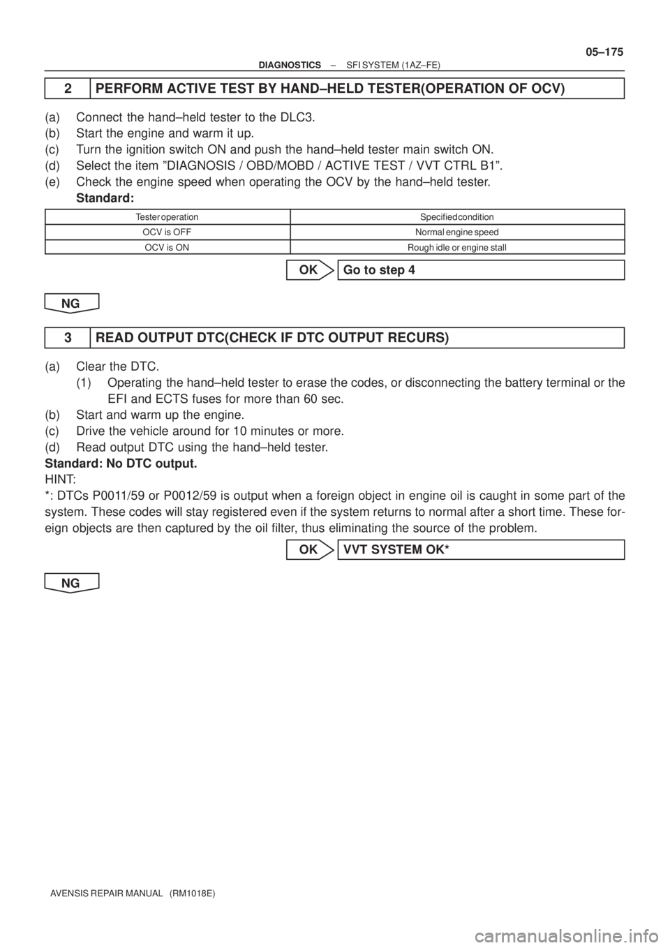
2 PERFORM ACTIVE TEST BY HAND±HELD TESTER(OPERATION OF OCV)
(a) Connect the hand±held tester to the DLC3.
(b) Start the engine and warm it up.
(c) Turn the ignition switch ON and push the hand±held tester main switch ON.
(d) Select the item ºDIAGNOSIS / OBD/MOBD / ACTIVE TEST / VVT CTRL B1º.
(e) Check the engine speed when operating the OCV by the hand±held tester.
Standard:
Tester operationSpecified condition
OCV is OFFNormal engine speed
OCV is ONRough idle or engine stall
OK Go to step 4
NG
3 READ OUTPUT DTC(CHECK IF DTC OUTPUT RECURS)
(a) Clear the DTC.
(1) Operating the hand±held tester to erase the codes, or disconnecting the battery terminal or the
EFI and ECTS fuses for more than 60 sec.
(b) Start and warm up the engine.
(c) Drive the vehicle around for 10 minutes or more.
(d) Read output DTC using the hand±held tester.
Standard: No DTC output.
HINT:
*: DTCs P0011/59 or P0012/59 is output when a foreign object in engine oil is caught in some part of the
system. These codes will stay registered even if the system returns to normal after a short time. These for-
eign objects are then captured by the oil filter, thus eliminating the source of the problem.
OK VVT SYSTEM OK*
NG
Page 3879 of 5135
A79111
OCV Signal Waveform1 msec./Division 5 V/
Division
GND
(A)(A) (A)
E13
OC1 +OC1±
05±176
±
DIAGNOSTICS SFI SYSTEM(1AZ±FE)
AVENSIS REPAIR MANUAL (RM1018E)
4CHECK ECM(OCV SIGNAL)
(a)Inspection using the oscilloscope.
(b)During idling, check the waveform between the terminals of the E13 ECM connector.
Standard:
Symbols (Terminal No.)Specified condition
OC1+ (E13±15) ± OC1± (E13±14)Correct waveform is as shown
HINT:
The waveform frequency (A) is lengthened as the engine speed
becomes higher.
NGCHECK AND REPLACE ECM (See page 01±32)
OK
5CHECK OIL CONTROL VALVE FILTER
NGREPLACE OIL CONTROL VALVE FILTER
OK
6CHECK CAMSHAFT TIMING OIL CONTROL VALVE ASSY(OCV) (See page 10±20)
OKGo to step 8
NG
7REPLACE CAMSHAFT TIMING OIL CONTROL VALVE ASSY(OCV)
GO
8CHECK CAMSHAFT TIMING GEAR ASSY (See page 14±171)
OK Go to step 10
NG
Page 3880 of 5135
±
DIAGNOSTICS SFI SYSTEM(1AZ±FE)
05±177
AVENSIS REPAIR MANUAL (RM1018E)
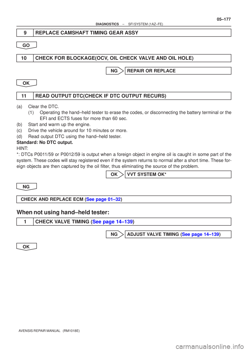
9REPLACE CAMSHAFT TIMING GEAR ASSY
GO
10CHECK FOR BLOCKAGE(OCV, OIL CHECK VALVE AND OIL HOLE)
NGREPAIR OR REPLACE
OK
11READ OUTPUT DTC(CHECK IF DTC OUTPUT RECURS)
(a)Clear the DTC. (1)Operating the hand±held tester to erase the codes, or disconnecting the batter\
y terminal or the
EFI and ECTS fuses for more than 60 sec.
(b)Start and warm up the engine.
(c)Drive the vehicle around for 10 minutes or more.
(d)Read output DTC using the hand±held tester.
Standard: No DTC output.
HINT:
*: DTCs P0011/59 or P0012/59 is output when a foreign object in engine oil is caught\
in some part of the
system. These codes will stay registered even if the system returns to normal a\
fter a short time. These for-
eign objects are then captured by the oil filter, thus eliminating the source of the problem.
OKVVT SYSTEM OK*
NG
CHECK AND REPLACE ECM (See page 01±32)
When not using hand±held tester:
1CHECK VALVE TIMING (See page 14±139)
NGADJUST VALVE TIMING (See page 14±139)
OK
Page 3881 of 5135
A76968
C2
(±) (+)
Camshaft Timing Oil Control Valve
05±178
± DIAGNOSTICSSFI SYSTEM (1AZ±FE)
AVENSIS REPAIR MANUAL (RM1018E)
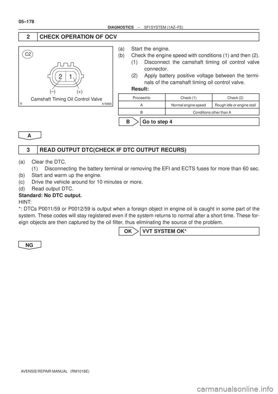
2 CHECK OPERATION OF OCV
(a) Start the engine.
(b) Check the engine speed with conditions (1) and then (2).
(1) Disconnect the camshaft timing oil control valve
connector.
(2) Apply battery positive voltage between the termi-
nals of the camshaft timing oil control valve.
Result:
Proceed toCheck (1)Check (2)
ANormal engine speedRough idle or engine stall
BConditions other than A
B Go to step 4
A
3 READ OUTPUT DTC(CHECK IF DTC OUTPUT RECURS)
(a) Clear the DTC.
(1) Disconnecting the battery terminal or removing the EFI and ECTS fuses for more than 60 sec.
(b) Start and warm up the engine.
(c) Drive the vehicle around for 10 minutes or more.
(d) Read output DTC.
Standard: No DTC output.
HINT:
*: DTCs P0011/59 or P0012/59 is output when a foreign object in engine oil is caught in some part of the
system. These codes will stay registered even if the system returns to normal after a short time. These for-
eign objects are then captured by the oil filter, thus eliminating the source of the problem.
OK VVT SYSTEM OK*
NG
Page 3882 of 5135
A79111
OCV Signal Waveform1 msec./Division 5 V/
Division
GND
(A)(A) (A)
E13
OC1 +OC1±
±
DIAGNOSTICS SFI SYSTEM(1AZ±FE)
05±179
AVENSIS REPAIR MANUAL (RM1018E)
4CHECK ECM(OCV SIGNAL)
(a)Inspection using the oscilloscope.
(b)During idling, check the waveform between the terminals
of the E13 ECM connector.
Standard:
Symbols (Terminal No.)Specified condition
OC1+ (E13±15) ± OC1± (E13±14)Correct waveform is as shown
HINT:
The waveform frequency (A) is lengthened as the engine speed
becomes higher.
NGCHECK AND REPLACE ECM (See page 01±32)
OK
5CHECK OIL CONTROL VALVE FILTER
NGREPLACE OIL CONTROL VALVE FILTER
OK
6CHECK CAMSHAFT TIMING OIL CONTROL VALVE ASSY(OCV) (See page 10±20)
OKGo to step 8
NG
7REPLACE CAMSHAFT TIMING OIL CONTROL VALVE ASSY(OCV)
GO
8CHECK CAMSHAFT TIMING GEAR ASSY (See page 14±171)
OK Go to step 10
NG