Page 2949 of 5135
550YZ±01
I35991
PulleyWeight Hub
Weight Hub
± HEATER & AIR CONDITIONERW/PULLEY COMPRESSOR ASSY (1ZZ±FE)
55±73
AVENSIS REPAIR MANUAL (RM1018E)
W/PULLEY COMPRESSOR ASSY (1ZZ±FE)
ON±VEHICLE INSPECTION
1. INSPECT W/PULLEY COMPRESSOR ASSY
(a) Check the operation.
(1) Start the engine.
(2) Inspect the weight hub.
Standard: The weight hub rotates along with the pulley
Page 2953 of 5135
550YX±01
I35991
PulleyWeight Hub
Weight Hub
± HEATER & AIR CONDITIONERW/PULLEY COMPRESSOR ASSY (3ZZ±FE)
55±69
AVENSIS REPAIR MANUAL (RM1018E)
W/PULLEY COMPRESSOR ASSY (3ZZ±FE)
ON±VEHICLE INSPECTION
1. INSPECT W/PULLEY COMPRESSOR ASSY
(a) Check the operation.
(1) Start the engine.
(2) Inspect the weight hub.
Standard: The weight hub rotates along with the pulley
Page 2977 of 5135

H4263210 m (33 ft) or moreBattery
SST(s)
H42633Weight
X Y
Y
H40013
Inner Diam.
Tires
(3 or More)Width 60±24
± SUPPLEMENTAL RESTRAINT SYSTEMHORN BUTTON ASSY
AVENSIS REPAIR MANUAL (RM1018E)
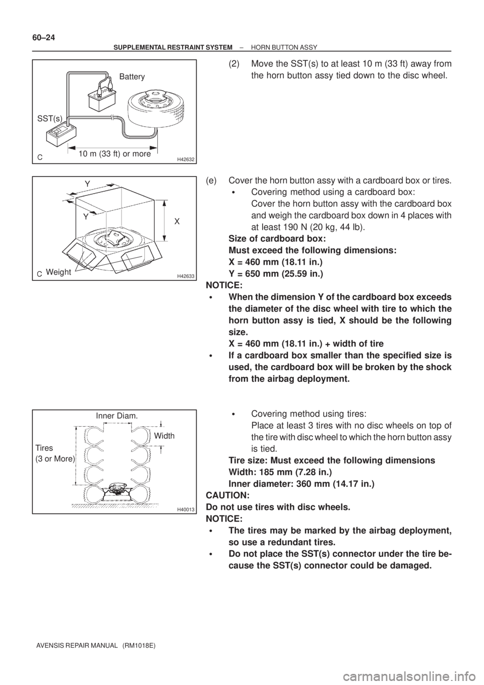
(2) Move the SST(s) to at least 10 m (33 ft) away from
the horn button assy tied down to the disc wheel.
(e) Cover the horn button assy with a cardboard box or tires.
�Covering method using a cardboard box:
Cover the horn button assy with the cardboard box
and weigh the cardboard box down in 4 places with
at least 190 N (20 kg, 44 lb).
Size of cardboard box:
Must exceed the following dimensions:
X = 460 mm (18.11 in.)
Y = 650 mm (25.59 in.)
NOTICE:
�When the dimension Y of the cardboard box exceeds
the diameter of the disc wheel with tire to which the
horn button assy is tied, X should be the following
size.
X = 460 mm (18.11 in.) + width of tire
�If a cardboard box smaller than the specified size is
used, the cardboard box will be broken by the shock
from the airbag deployment.
�Covering method using tires:
Place at least 3 tires with no disc wheels on top of
the tire with disc wheel to which the horn button assy
is tied.
Tire size: Must exceed the following dimensions
Width: 185 mm (7.28 in.)
Inner diameter: 360 mm (14.17 in.)
CAUTION:
Do not use tires with disc wheels.
NOTICE:
�The tires may be marked by the airbag deployment,
so use a redundant tires.
�Do not place the SST(s) connector under the tire be-
cause the SST(s) connector could be damaged.
Page 3106 of 5135

650SV±01
I33423
V LH LineV RH LineV Line
Ground
H Line
± LIGHTINGHEADLAMP UNIT LH
65±19
AVENSIS REPAIR MANUAL (RM1018E)
ADJUSTMENT
1. HEADLIGHT AIM ONLY
HINT:
�Perform aiming adjustment with Low±beam.
�Since the Low±beam light and the High±beam light is a
unit, if aiming on either side is connect, the other side
should also be connect.
However, check both beams just to make sure.
(a) Prepare vehicle in the following conditions.
�Check that any damage or deformation does not exist on
the body around the headlights.
�Fuel tank is full.
�The tire inflation pressure is at the specified level.
�Vehicle is parked at a level surface.
�A person having an average weight sits in the driver's
seat.
�Vehicle is bounced up and down to stabilize the suspen-
sion to the normal position.
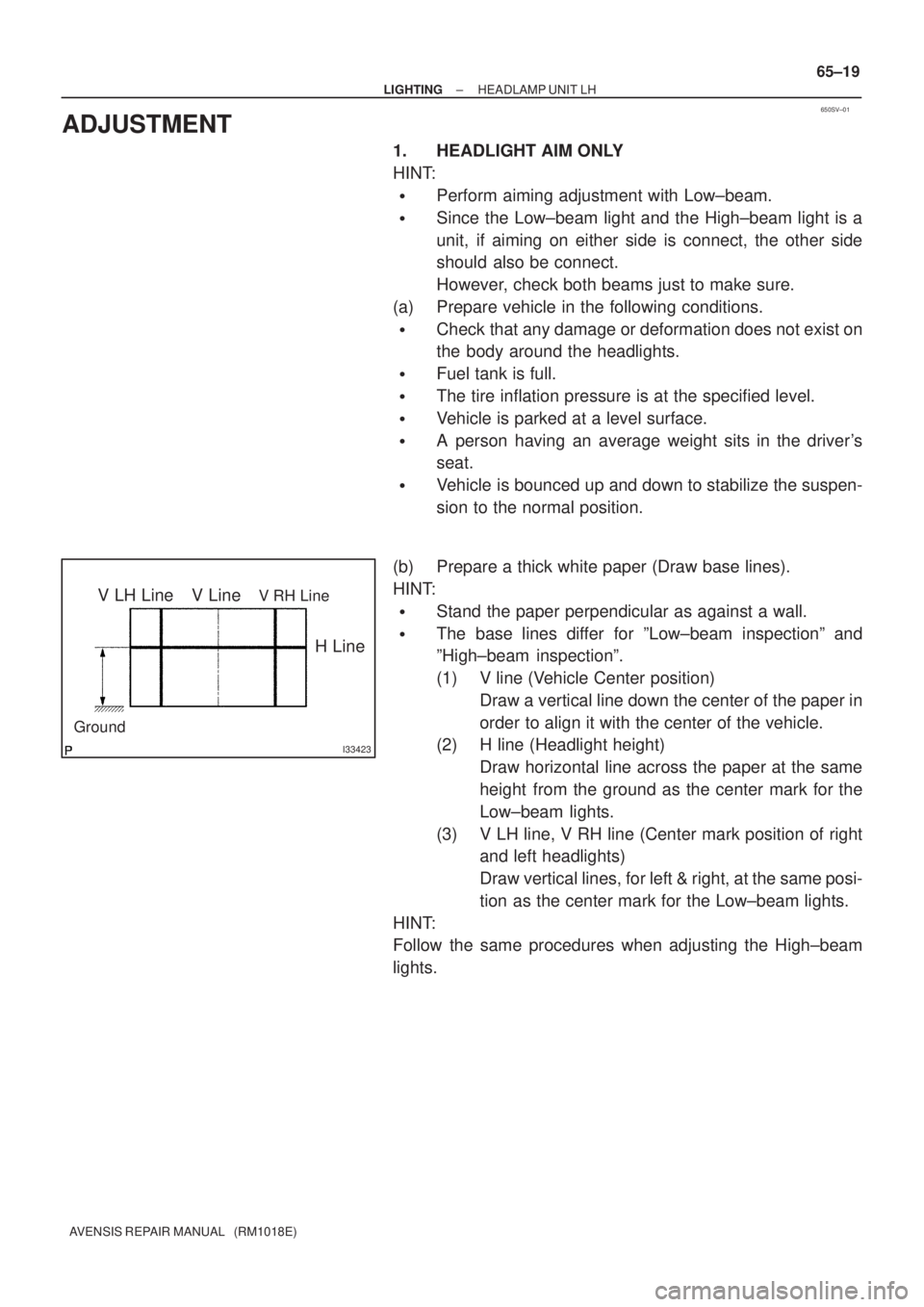
(b) Prepare a thick white paper (Draw base lines).
HINT:
�Stand the paper perpendicular as against a wall.
�The base lines differ for ºLow±beam inspectionº and
ºHigh±beam inspectionº.
(1) V line (Vehicle Center position)
Draw a vertical line down the center of the paper in
order to align it with the center of the vehicle.
(2) H line (Headlight height)
Draw horizontal line across the paper at the same
height from the ground as the center mark for the
Low±beam lights.
(3) V LH line, V RH line (Center mark position of right
and left headlights)
Draw vertical lines, for left & right, at the same posi-
tion as the center mark for the Low±beam lights.
HINT:
Follow the same procedures when adjusting the High±beam
lights.
Page 3462 of 5135

010B9±09
± INTRODUCTIONTERMS
01±7
1AZ±FSE ENGINE REPAIR MANUAL (RM1019E)
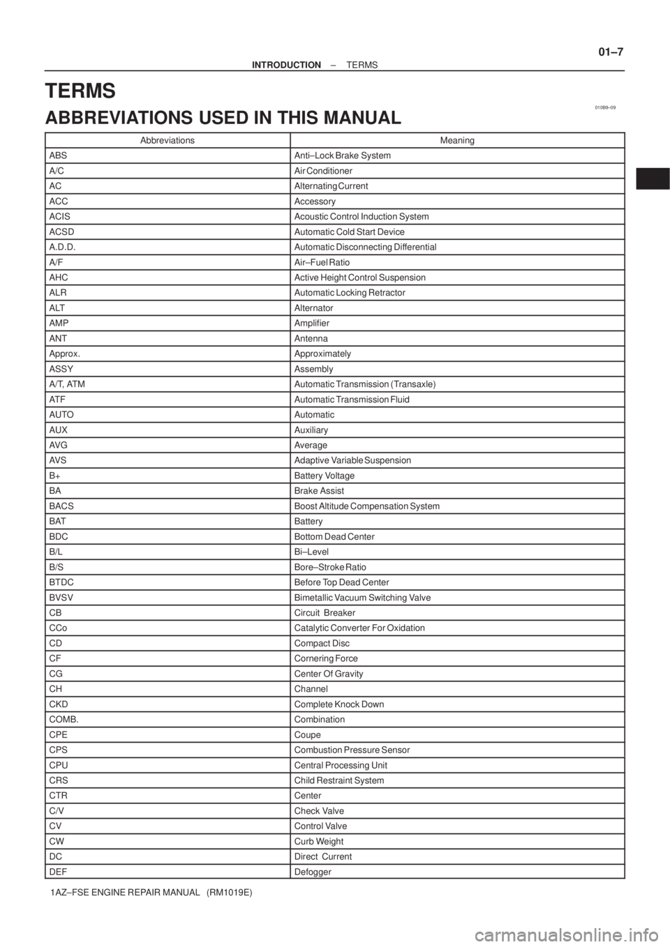
TERMS
ABBREVIATIONS USED IN THIS MANUAL
AbbreviationsMeaning
ABSAnti±Lock Brake System
A/CAir Conditioner
ACAlternating Current
ACCAccessory
ACISAcoustic Control Induction System
ACSDAutomatic Cold Start Device
A.D.D.Automatic Disconnecting Differential
A/FAir±Fuel Ratio
AHCActive Height Control Suspension
ALRAutomatic Locking Retractor
ALTAlternator
AMPAmplifier
ANTAntenna
Approx.Approximately
ASSYAssembly
A/T, ATMAutomatic Transmission (Transaxle)
AT FAutomatic Transmission Fluid
AUTOAutomatic
AUXAuxiliary
AV GAverage
AV SAdaptive Variable Suspension
B+Battery Voltage
BABrake Assist
BACSBoost Altitude Compensation System
BATBattery
BDCBottom Dead Center
B/LBi±Level
B/SBore±Stroke Ratio
BTDCBefore Top Dead Center
BVSVBimetallic Vacuum Switching Valve
CBCircuit Breaker
CCoCatalytic Converter For Oxidation
CDCompact Disc
CFCornering Force
CGCenter Of Gravity
CHChannel
CKDComplete Knock Down
COMB.Combination
CPECoupe
CPSCombustion Pressure Sensor
CPUCentral Processing Unit
CRSChild Restraint System
CTRCenter
C/VCheck Valve
CVControl Valve
CWCurb Weight
DCDirect Current
DEFDefogger
Page 3474 of 5135

170FM±01
A77229
A77233
A77230
Mark
A77231
17±2
± LUBRICATIONOIL PUMP ASSY
1AZ±FSE ENGINE REPAIR MANUAL (RM1019E)
OVERHAUL
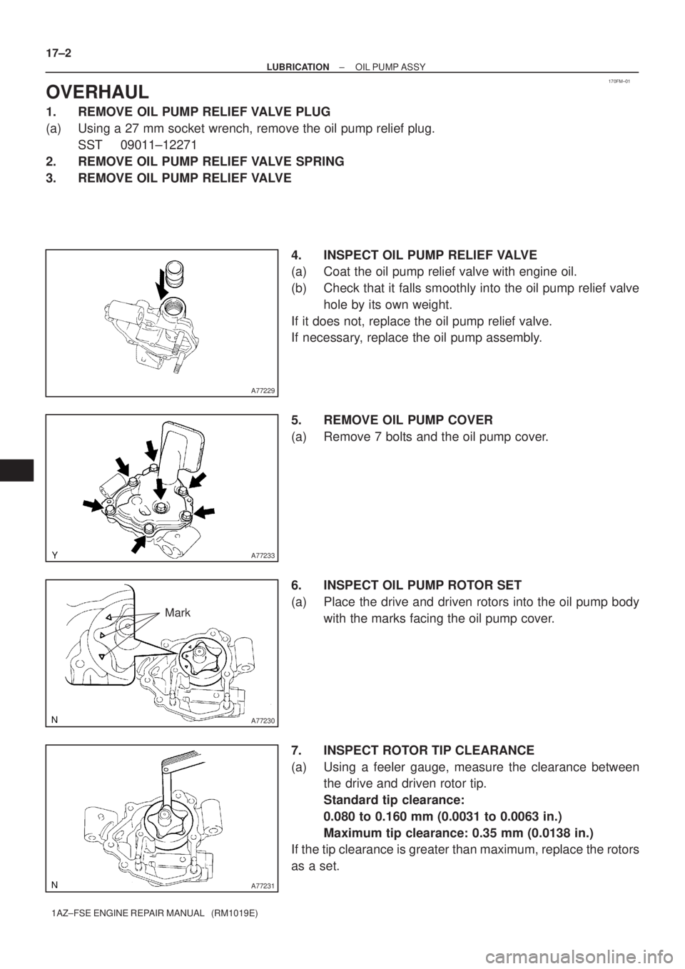
1. REMOVE OIL PUMP RELIEF VALVE PLUG
(a) Using a 27 mm socket wrench, remove the oil pump relief plug.
SST 09011±12271
2. REMOVE OIL PUMP RELIEF VALVE SPRING
3. REMOVE OIL PUMP RELIEF VALVE
4. INSPECT OIL PUMP RELIEF VALVE
(a) Coat the oil pump relief valve with engine oil.
(b) Check that it falls smoothly into the oil pump relief valve
hole by its own weight.
If it does not, replace the oil pump relief valve.
If necessary, replace the oil pump assembly.
5. REMOVE OIL PUMP COVER
(a) Remove 7 bolts and the oil pump cover.
6. INSPECT OIL PUMP ROTOR SET
(a) Place the drive and driven rotors into the oil pump body
with the marks facing the oil pump cover.
7. INSPECT ROTOR TIP CLEARANCE
(a) Using a feeler gauge, measure the clearance between
the drive and driven rotor tip.
Standard tip clearance:
0.080 to 0.160 mm (0.0031 to 0.0063 in.)
Maximum tip clearance: 0.35 mm (0.0138 in.)
If the tip clearance is greater than maximum, replace the rotors
as a set.
Page 4733 of 5135

C83155
F40218
SST
C91598
C86265
30−6
− DRIVE SHAFT / PROPELLER SHAFTFRONT DRIVE SHAFT (2AZ−FSE)
AVENSIS Supplement (RM1045E)
11. REMOVE FRONT DRIVE SHAFT ASSY RH (RH DRIVE
SHAFT)
(a) Remove the 2 bolts and pull out the drive shaft together
with the center bearing bracket.
(b) Remove the drive shaft from the transaxle.
NOTICE:
SBe careful not to damage the oil seal, boot and dust
cover.
SBe careful not to drop the drive shaft assy.
12. FIX FRONT AXLE HUB LH BEARING
NOTICE:
The hub bearing may become damaged if subjected to the
vehicle weight. For example, moving the vehicle with the
drive shaft removed.
Therefore, if it is absolutely necessary to place the vehicle
weight on the hub bearing, first support it with SST.
SST 09608−16042 (09608−02021, 09608−02041)
13. INSPECT FRONT DRIVE SHAFT ASSY LH
(a) Check that there is no excessive play in the radial direc-
tion of the outboard joint.
(b) Check that the inboard joint slides smoothly in the thrust
direction.
(c) Check that there is no excessive play in the radial direc-
tion of the inboard joint.
(d) Check the boots for damage.
NOTICE:
Keep the drive shaft assy level during inspection.
14. REMOVE FRONT AXLE INBOARD JOINT BOOT
CLAMP
(a) Using pliers, remove the inboard joint boot LH No.2 clamp
as shown in the illustration.
(b) Remove the inboard joint boot LH clamp ifollwng the
same procedure as for the inboard joint boot LH No.2
clamp.
15. REMOVE FR AXLE INBOARD JOINT BOOT
(a) Remove the inboard joint boot from the inboard joint assy LH.