Page 2536 of 5135

300JX±01
������F45751
SST
F13686
Hold
Turn
C80291
30±6
± DRIVE SHAFT / PROPELLER SHAFTFRONT DRIVE SHAFT
AVENSIS REPAIR MANUAL (RM1018E)
OVERHAUL
HINT:
Overhaul the RH side by the same procedures as the LH side.
1. DRAIN AUTOMATIC TRANSAXLE FLUID (A/T TRANSAXLE)
(a) Remove the drain plug and gasket, and then drain the ATF.
(b) Install a new gasket and drain plug.
Torque: 49 N�m (500 kgf�cm, 36 ft�lbf)
2. DRAIN MANUAL TRANSAXLE OIL (M/T TRANSAXLE)
(a) Remove the filler plug and gasket.
(b) Remove the drain plug and gasket.
(c) Install 2 new gaskets, drain plug and filler plug.
Torque:
C50/C250: 39 N�m (400 kgf�cm, 29 ft�lbf)
E354/E357: 49 N�m (500 kgf�cm, 36 ft�lbf)
3. REMOVE FRONT WHEEL
4. REMOVE ENGINE UNDER COVER LH
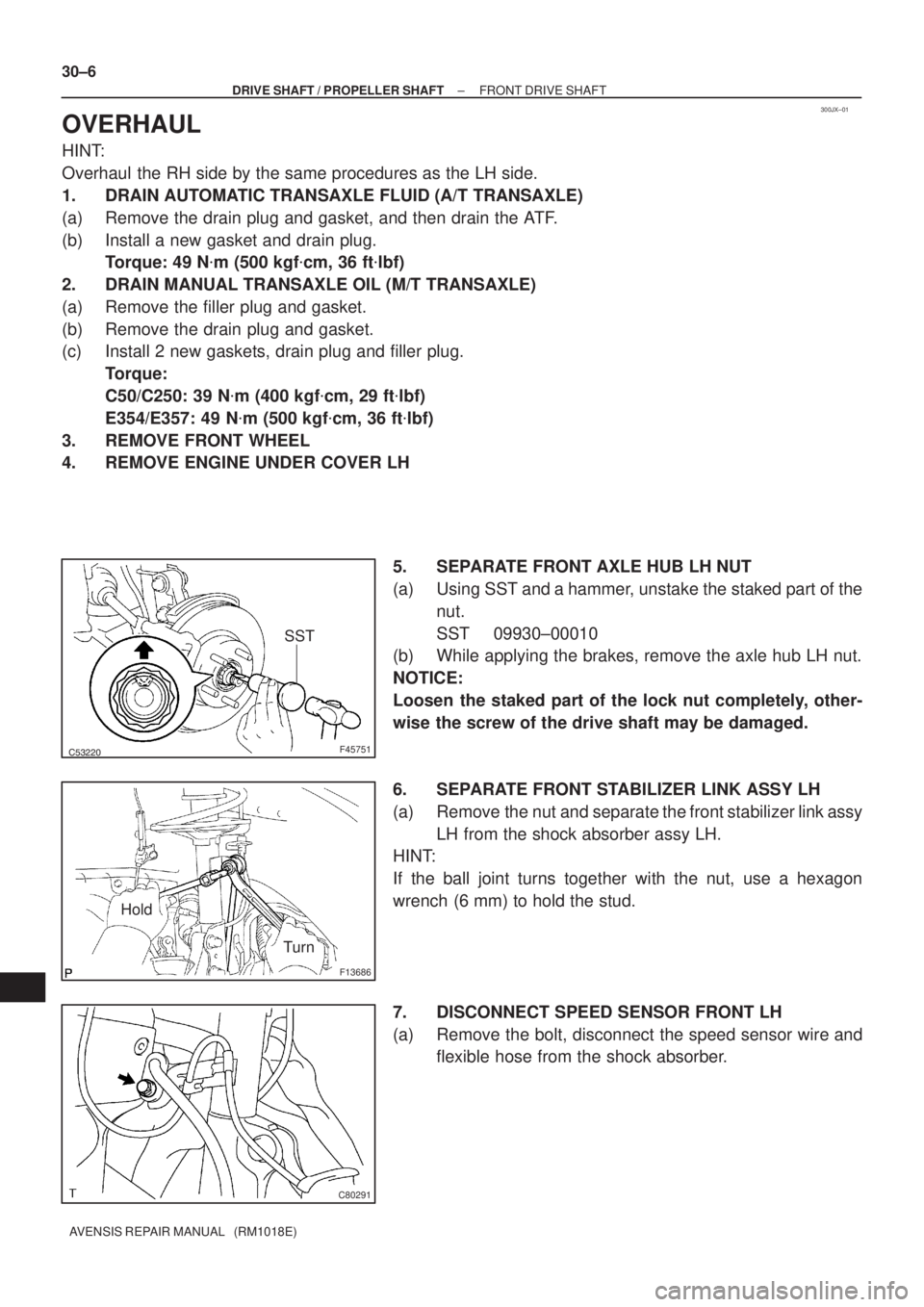
5. SEPARATE FRONT AXLE HUB LH NUT
(a) Using SST and a hammer, unstake the staked part of the
nut.
SST 09930±00010
(b) While applying the brakes, remove the axle hub LH nut.
NOTICE:
Loosen the staked part of the lock nut completely, other-
wise the screw of the drive shaft may be damaged.
6. SEPARATE FRONT STABILIZER LINK ASSY LH
(a) Remove the nut and separate the front stabilizer link assy
LH from the shock absorber assy LH.
HINT:
If the ball joint turns together with the nut, use a hexagon
wrench (6 mm) to hold the stud.
7. DISCONNECT SPEED SENSOR FRONT LH
(a) Remove the bolt, disconnect the speed sensor wire and
flexible hose from the shock absorber.
Page 2596 of 5135
±
BRAKE BRAKE SYSTEM
32±3
AVENSIS REPAIR MANUAL (RM1018E)
Noise from brakes
1. Pad (Cracked or distorted)
2. Installation bolt (Loose)
3. Disc (Scored)
4. Pad support plate (Loose)
5. Sliding pin (Worn)
6. Pad (dirty)
7. Pad(Glazed)32±41
32±47
32±41
32±47
32±41
32±47
32±41
32±47
32±41
32±47
32±41
32±47
32±41
32±47
Page 2607 of 5135
3201P±05
G23166
F40024
G23165
G23165
± BRAKESPEED SENSOR FRONT LH
32±59
AVENSIS REPAIR MANUAL (RM1018E)
SPEED SENSOR FRONT LH
REPLACEMENT
HINT:
Replace the RH side by using the same procedures as those for the LH side.
1. REMOVE FRONT WHEEL
2. REMOVE FRONT FENDER LINER LH
3. REMOVE SPEED SENSOR FRONT LH
(a) Disconnect the resin clip and speed sensor wire harness
from the body and clamp.
(b) Disconnect the speed sensor connector.
(c) Remove the 2 clamp bolts holding the sensor harness
from the body and shock absorber.
(d) Remove the bolt and separate the speed sensor front LH.
NOTICE:
Prevent foeingn matter from attaching to the sensor tip.
4. INSTALL SPEED SENSOR FRONT LH
(a) Install the speed sensor front LH with the bolt.
Torque: 8.0 N�m (82 kgf�cm, 71 in.�lbf)
NOTICE:
Prevent foeingn matter from attaching to the sensor tip.
Page 2650 of 5135

400D8±02
± AUTOMATIC TRANSMISSION / TRANSAUTOMATIC TRANSAXLE ASSY (ATM)
40±1
AVENSIS REPAIR MANUAL (RM1018E)
AUTOMATIC TRANSAXLE ASSY (ATM)
PRECAUTION
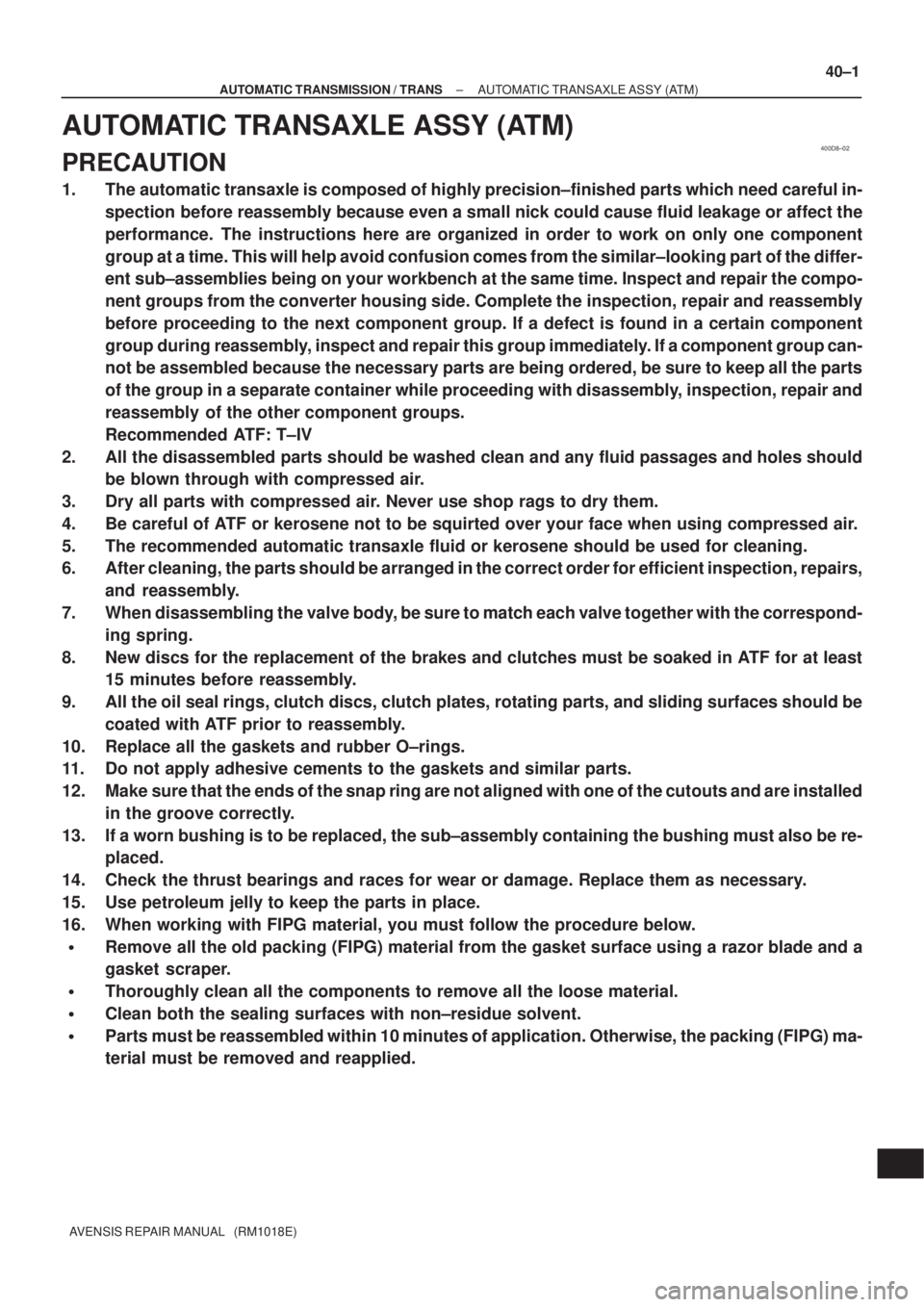
1. The automatic transaxle is composed of highly precision±finished parts which need careful in-
spection before reassembly because even a small nick could cause fluid leakage or affect the
performance. The instructions here are organized in order to work on only one component
group at a time. This will help avoid confusion comes from the similar±looking part of the differ-
ent sub±assemblies being on your workbench at the same time. Inspect and repair the compo-
nent groups from the converter housing side. Complete the inspection, repair and reassembly
before proceeding to the next component group. If a defect is found in a certain component
group during reassembly, inspect and repair this group immediately. If a component group can-
not be assembled because the necessary parts are being ordered, be sure to keep all the parts
of the group in a separate container while proceeding with disassembly, inspection, repair and
reassembly of the other component groups.
Recommended ATF: T±IV
2. All the disassembled parts should be washed clean and any fluid passages and holes should
be blown through with compressed air.
3. Dry all parts with compressed air. Never use shop rags to dry them.
4. Be careful of ATF or kerosene not to be squirted over your face when using compressed air.
5. The recommended automatic transaxle fluid or kerosene should be used for cleaning.
6. After cleaning, the parts should be arranged in the correct order for efficient inspection, repairs,
and reassembly.
7. When disassembling the valve body, be sure to match each valve together with the correspond-
ing spring.
8. New discs for the replacement of the brakes and clutches must be soaked in ATF for at least
15 minutes before reassembly.
9. All the oil seal rings, clutch discs, clutch plates, rotating parts, and sliding surfaces should be
coated with ATF prior to reassembly.
10. Replace all the gaskets and rubber O±rings.
11. Do not apply adhesive cements to the gaskets and similar parts.
12. Make sure that the ends of the snap ring are not aligned with one of the cutouts and are installed
in the groove correctly.
13. If a worn bushing is to be replaced, the sub±assembly containing the bushing must also be re-
placed.
14. Check the thrust bearings and races for wear or damage. Replace them as necessary.
15. Use petroleum jelly to keep the parts in place.
16. When working with FIPG material, you must follow the procedure below.
�Remove all the old packing (FIPG) material from the gasket surface using a razor blade and a
gasket scraper.
�Thoroughly clean all the components to remove all the loose material.
�Clean both the sealing surfaces with non±residue solvent.
�Parts must be reassembled within 10 minutes of application. Otherwise, the packing (FIPG) ma-
terial must be removed and reapplied.
Page 3078 of 5135
610E8±01
B69710
± SEAT BELTFRONT SEAT BELT
61±5
AVENSIS REPAIR MANUAL (RM1018E)
FRONT SEAT BELT
PRECAUTION
CAUTION:
Replace the faulty parts of the seat belt systems (outer belt, inner belt, bolts, nuts, adjustable shoul-
der anchor, tether anchor hardware, sill±bar, etc.)
Seat belt systems not in use at the time of a collision should also be inspected and replaced if found
to be damaged or working improperly.
1. RUNNING TEST (IN SAFE AREA)
(a) Fasten the front seat belts.
(b) Drive the car at 16 km/h (10 mph) and slam on the brakes.
Check the belt locks and cannot be extended at this time.
HINT:
Conduct this test in a safe area. If the belt does not lock, remove
the belt assembly and perform the following static check. Also
whenever installing a new belt assembly, verify the proper op-
eration before installation.
Page 3924 of 5135

±
DIAGNOSTICS SFI SYSTEM(1AZ±FSE)
05±475
AVENSIS REPAIR MANUAL (RM1018E)
DTCP0724BRAKE SWITCH ºBº CIRCUIT HIGH
CIRCUIT DESCRIPTION
This STP signal is used to detect that the brakes have been applied. The STP\
signal voltage is the same
as the one supplied to the stop lights.
The STP signal is used mainly to control the fuel cut±off engine speed (The fuel cut±off engine speed is re-
duced slightly when the vehicle is braking).
DTC No.DTC Detection ConditionTrouble Area
P0724The stop light switch does not turn off even the vehicle is driv-
en. (2 trip detection logic)�Short in stop light switch signal circuit
� Stop light switch
� ECM
WIRING DIAGRAM
Refer to DTC P0504 on page 05±455.
INSPECTION PROCEDURE
HINT:
Read freeze frame data using the hand±held tester. Freeze frame data records the engine conditions when
a malfunction is detected. When troubleshooting, it is useful for determi\
ning whether the vehicle was running
or stopped, the engine was warmed up or not, the air±fuel ratio was lea\
n or rich, etc. at the time of the mal-
function.
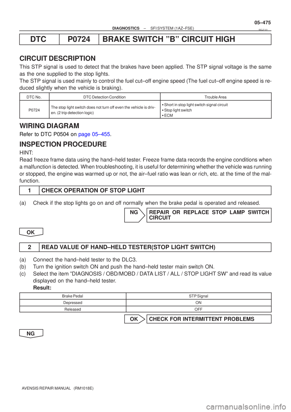
1 CHECK OPERATION OF STOP LIGHT
(a) Check if the stop lights go on and off normally when the brake pedal is operated and released.
NG REPAIR OR REPLACE STOP LAMP SWITCHCIRCUIT
OK
2 READ VALUE OF HAND±HELD TESTER(STOP LIGHT SWITCH)
(a) Connect the hand±held tester to the DLC3.
(b) Turn the ignition switch ON and push the hand±held tester main switch \
ON.
(c) Select the item ºDIAGNOSIS / OBD/MOBD / DATA LIST / ALL / STOP LIGHT SWº and read its value displayed on the hand±held tester.
Result:
Brake PedalSTP Signal
DepressedON
ReleasedOFF
OK CHECK FOR INTERMITTENT PROBLEMS
NG
05CJ7±01
Page 3989 of 5135
F45135
B±R
DH DA18 2Driver Side J/B
IGNEBDW S120
IE118 4
B±W
C11 C11Combination Meter
BrakeSkid Control ECU
with Actuator
P 22
17
C10
AM2
4B 4A11IG2
A 1
2 AM2
3
IK 1A
Engine Room R/B No.3 Engine Room R/B No.1 & Engine Room J/B No.1
1
3 Engine Room J/B No.41
IO ILJ15
J/C
Battery
*1: 1AZ±FSE
*2: 1CD±FTV
*3: LHD
*4: RHD(*3) (*4) (*3) (*4)B±W CA CA
J8 J26 J8 J26J/C
B±R
IE4 IP111
(*3) (*4) B±R
B (*2)B±G (*1)
B (*2)
FL MAINB±G (*1)
W±B (*3 *2)
W±B (*3 *1)A A
AAJ17
J/C
J16
J/C W±B
(*3) W±B (*4) W±B (*4)
I13
Ignition SW
46P
± DIAGNOSTICSABS WITH EBD & BA & TRC & VSC SYSTEM
05±841
AVENSIS REPAIR MANUAL (RM1018E)
WIRING DIAGRAM
Page 4518 of 5135
![TOYOTA AVENSIS 2005 Service Repair Manual 05−580−
DIAGNOSTICS ELECTRONIC CONTROLLED AUTOMATIC
TRANSAXLE [ECT] (U 151E)
AVENSIS Supplement (RM 1045E)
DTC P0724 BRAKE SWITCH ”B” CIRCUIT HIGH
CIRCUIT DESCRIPTION
The purpose of this circ TOYOTA AVENSIS 2005 Service Repair Manual 05−580−
DIAGNOSTICS ELECTRONIC CONTROLLED AUTOMATIC
TRANSAXLE [ECT] (U 151E)
AVENSIS Supplement (RM 1045E)
DTC P0724 BRAKE SWITCH ”B” CIRCUIT HIGH
CIRCUIT DESCRIPTION
The purpose of this circ](/manual-img/14/57441/w960_57441-4517.png)
05−580−
DIAGNOSTICS ELECTRONIC CONTROLLED AUTOMATIC
TRANSAXLE [ECT] (U 151E)
AVENSIS Supplement (RM 1045E)
DTC P0724 BRAKE SWITCH ”B” CIRCUIT HIGH
CIRCUIT DESCRIPTION
The purpose of this circuit is to prevent the engine from stalling while driving in lock −up condition, when
brakes are suddenly applied.
When the brake pedal is depressed, this switch sends a signals to the ECM. Then the ECM cancels the op-
eration of the lock −up clutch while braking is in progress.
DTC No.DTC Detecting ConditionTrouble Area
P0724
The stop light switch remains ON even when the vehicle is
driven in a GO (30 km/h) and STOP (3 km/h) fashion 10 times.
(2 −trip detection logic).S Short in stop light switch signal circuit
S Stop light switch
S ECM
MONITOR DESCRIPTION
This DTC indicates that the stop light switch remains on. When the stop light switch remains ON during ”stop
and go” driving, the ECM interprets this as a fault in the stop light switch and the MIL comes on and the ECM
stores the DTC. The vehicle must stop (less than 3 km/h (2 mph)) and go (30 km/h ( 19 mph) or more) ten
times for two driving cycles in order to detect malfunction.
WIRING DIAGRAM
See page 05 −1 85.
05JLI −01