Page 1748 of 5135

I36055
05±1724
±
DIAGNOSTICS CRUISE CONTROL SYSTEM
AVENSIS REPAIR MANUAL (RM1018E)
INSPECTION PROCEDURE
HINT:
In case of using the hand±held tester, start the inspection from step 1, and in case of not using the hand±held
tester, start from step 2.
1READ VALUE OF HAND±HELD TESTER
(a)Connect the hand±held tester to the DLC3.
(b)Turn the ignition switch to the ON position, and turn the hand±held te\
ster main switch ON.
(c)Select the item ºCCS READYº in the DATA LIST and read its prompts displayed on the hand±held tes- ter.
ItemMeasurement Item /
Display (Range)Normal Condition
CCS READY MCruise control system standby
condition (Main CPU) / ON or OFFON � OFF: Change ON/OFF
each time Main SW is pushed in.
CCS READY SCruise control system standby
condition (Sub CPU) / ON or OFFON � OFF: Change ON/OFF
each time Main SW is pushed in.
NGPROCEED TO NEXT CIRCUIT INSPECTION SHOWN ON PROBLEM SYMPTOMS TABLE
(See page 05±1709)
OK
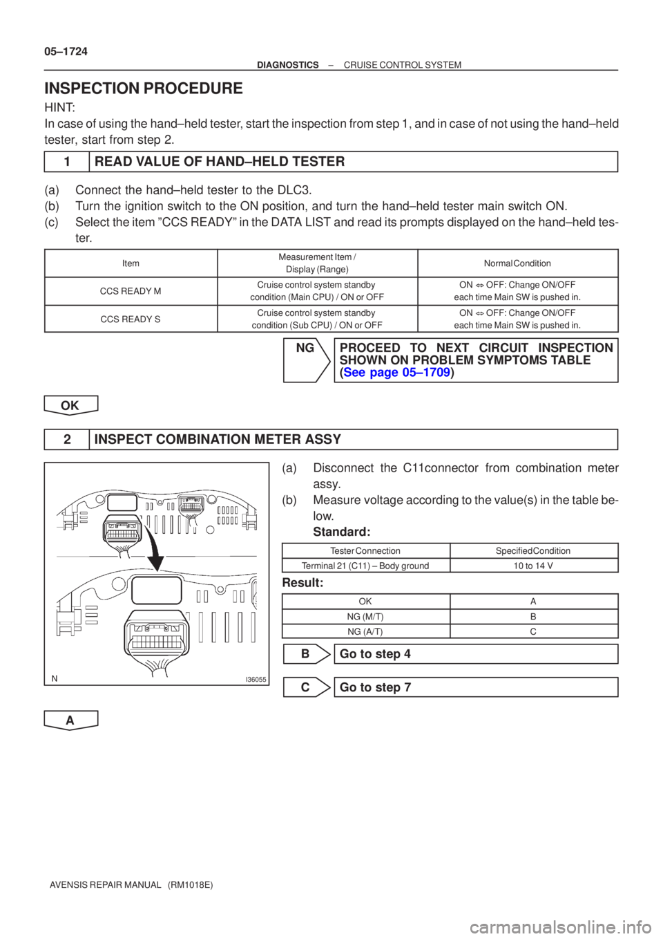
2 INSPECT COMBINATION METER ASSY
(a) Disconnect the C11connector from combination meter assy.
(b) Measure voltage according to the value(s) in the table be- low.
Standard:
Tester ConnectionSpecified Condition
Terminal 21 (C11) ± Body ground10 to 14 V
Result:
OKA
NG (M/T)B
NG (A/T)C
B Go to step 4
C Go to step 7
A
Page 1749 of 5135
I36055
E67361
Push inFree
1 2
± DIAGNOSTICSCRUISE CONTROL SYSTEM
05±1725
AVENSIS REPAIR MANUAL (RM1018E)
3 INSPECT COMBINATION METER ASSY
(a) Disconnect the C11 connector from the combination me-
ter.
(b) Measure the resistance according to the value(s) in the
table below.
Standard:
Tester ConnectionSpecified Condition
Terminal 5 (C11) ± Body ground10 k� or higher
NG REPAIR OR REPLACE HARNESS OR
CONNECTOR
OK
REPAIR OR REPLACE COMBINATION METER ASSY
4 INSPECT CLUTCH START SWITCH ASSY
(a) Disconnect the clutch start switch assy connector.
(b) Measure the resistance according to the value(s) in the
table below.
Standard:
Switch conditionTester connectionSpecification
Switch pin free1 ± 210 k� or higher
Switch pin pushed in1 ± 21 � or less
NG INSPECT CLUTCH START SWITCH ASSY
OK
Page 1750 of 5135

05±1726
±
DIAGNOSTICS CRUISE CONTROL SYSTEM
AVENSIS REPAIR MANUAL (RM1018E)
5CHECK HARNESS AND CONNECTOR(COMBINAITION METER ASSY ± CLUTCH START SWITCH ASSY)
(a)Disconnect the combination meter connector and clutch start switch connector.
(b)Measure the resistance according to the value(s) in the table below.
Standard:
Tester connectionConditionSpecification
Combination meter (C11±21) ± Clutch
start switch (C9±1)Always1 � or less
(c)Measure the resistance according to the value(s) in the table below.
Standard:
Tester connectionConditionSpecification
Clutch start switch (C9±1) ± Body groundAlways10 k� or higher
NGREPAIR OR REPLACE HARNESS OR
CONNECTOR
OK
6CHECK HARNESS AND CONNECTOR(CLUTCH START SWITCH ASSY ± ECM)
(a)Disconnect the clutch start switch connector and ECM connector.
(b)Measure the resistance according to the value(s) in the table below. Standard:
Tester connectionConditionSpecification
Clutch start switch (C9±2) ± D (E11±10)Always1 � or less
(c)Measure the resistance according to the value(s) in the table below.
Standard:
Tester connectionConditionSpecification
D (E11±10) ± Body groundAlways10 k� or higher
NGREPAIR OR REPLACE HARNESS OR
CONNECTOR
OK
PROCEED TO NEXT CIRCUIT INSPECTION SHOWN ON PROBLEM SYMPTOMS TABLE (See page
05±1709)
Page 1751 of 5135

�
� � � � �
� �
C53270
± DIAGNOSTICSCRUISE CONTROL SYSTEM
05±1727
AVENSIS REPAIR MANUAL (RM1018E)
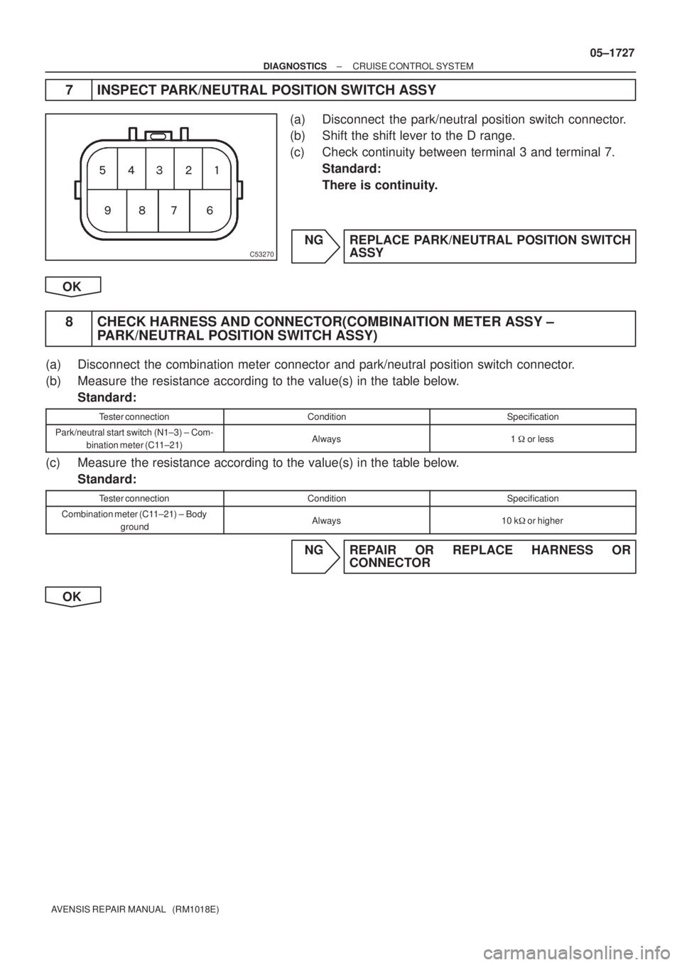
7 INSPECT PARK/NEUTRAL POSITION SWITCH ASSY
(a) Disconnect the park/neutral position switch connector.
(b) Shift the shift lever to the D range.
(c) Check continuity between terminal 3 and terminal 7.
Standard:
There is continuity.
NG REPLACE PARK/NEUTRAL POSITION SWITCH
ASSY
OK
8 CHECK HARNESS AND CONNECTOR(COMBINAITION METER ASSY ±
PARK/NEUTRAL POSITION SWITCH ASSY)
(a) Disconnect the combination meter connector and park/neutral position switch connector.
(b) Measure the resistance according to the value(s) in the table below.
Standard:
Tester connectionConditionSpecification
Park/neutral start switch (N1±3) ± Com-
bination meter (C11±21)Always1 � or less
(c) Measure the resistance according to the value(s) in the table below.
Standard:
Tester connectionConditionSpecification
Combination meter (C11±21) ± Body
groundAlways10 k� or higher
NG REPAIR OR REPLACE HARNESS OR
CONNECTOR
OK
Page 1752 of 5135
05±1728
±
DIAGNOSTICS CRUISE CONTROL SYSTEM
AVENSIS REPAIR MANUAL (RM1018E)
9CHECK HARNESS AND CONNECTOR(PARK/NEUTRAL POSITION SWITCH ASSY ± ECM)
(a)Disconnect the ECM connector and park/neutral position switch connector.
(b)Measure the resistance according to the value(s) in the table below.
Standard:
Tester connectionConditionSpecification
Park/neutral start switch (N1±7) ± D
(E11±10)Always1 � or less
(c)Measure the resistance according to the value(s) in the table below.
Standard:
Tester connectionConditionSpecification
D (E11±10) ± Body groundAlways10 k� or higher
NGREPAIR OR REPLACE HARNESS OR
CONNECTOR
OK
PROCEED TO NEXT CIRCUIT INSPECTION SHOWN ON PROBLEM SYMPTOMS TABLE
(See page 05±1709)
Page 1753 of 5135
I35711
C14
Combination SW
CANCEL SET/COASTRES/ACC
CRUISE
CCS
CCSW24
E11
J/C
E J13
J13
J13
J12 ECC 3
BR
BR
BR2 1AZ±FSE
ECU
EE
E
E
D
Cruise Control Main Switch Assy 05±1718
± DIAGNOSTICSCRUISE CONTROL SYSTEM
AVENSIS REPAIR MANUAL (RM1018E)
CRUISE CONTROL SWITCH CIRCUIT
CIRCUIT DESCRIPTION
This circuit carries the SET/COAST, RES/ACC and CANCEL signals (each voltage) to the ECM.
WIRING DIAGRAM
05C4T±01
Page 1754 of 5135
I35711
C14
Combination SW
CANCEL SET/COASTRES/ACC
CRUISE
CCS
CCSW24
E11
J/C
E J13
J13
J13
J12 ECC 3
BR
BR
BR2 1CD±FTV
ECU
E1
E
E
D
Cruise Control Main Switch Assy
± DIAGNOSTICSCRUISE CONTROL SYSTEM
05±1719
AVENSIS REPAIR MANUAL (RM1018E)
Page 1755 of 5135
05±1720
± DIAGNOSTICSCRUISE CONTROL SYSTEM
AVENSIS REPAIR MANUAL (RM1018E)
INSPECTION PROCEDURE
HINT:
In case of using the hand±held tester, start the inspection from step 1, and in case of not using the hand±held
tester, start from step 2.
1 READ VALUE OF HAND±HELD TESTER
(a) Connect the hand±held tester to the DLC3.
(b) Turn the ignition switch to the ON position, and turn the hand±held tester main switch ON.
(c) Select the item ºCCS READYº in the DATA LIST and read its prompts displayed on the hand±held tes-
ter.
ItemMeasurement Item /
Display (Range)Normal ConditionDiagnostic Note
CCS READY MCruise control system standby
condition (Main CPU) / ON or OFFON ± OFF : Change ON/OFF
each time Main SW is pushed in.º1º
CCS READY SCruise control system standby
condition (Sub CPU) / ON or OFFON ± OFF : Change ON/OFF
each time Main SW is pushed in.º1º
NG Go to step 2
OK
PROCEED TO NEXT CIRCUIT INSPECTION SHOWN ON PROBLEM SYMPTOMS TABLE