Page 1738 of 5135
B68375
E6
Engine Hood Courtesy Switch
W±B
1 3IO15
DSWH
34 L±RT6
Theft Warning ECU Assy
ECL±R
B67861
Free
(ON)
Pushed
(OFF)
05±1642
± DIAGNOSTICSTHEFT DETERRENT SYSTEM
AVENSIS REPAIR MANUAL (RM1018E)
ENGINE HOOD COURTESY SWITCH CIRCUIT
CIRCUIT DESCRIPTION
The engine hood courtesy switch is installed together with the hood lock assy. This switch comes on when
the engine hood is opened and goes off when the engine hood is closed.
WIRING DIAGRAM
INSPECTION PROCEDURE
1 INSPECT ENGINE HOOD COURTESY SWITCH
(a) Remove the engine hood courtesy switch from the hood
lock assy.
(b) Check the resistance.
Tester ConnectionSwitch PositionSpecified Condition
13Pushed (OFF (Lock))10 k� or higher1 ± 3Free (ON (Unlock))Below 1 �
NG REPAIR OR REPLACE ENGINE HOOD
COURTESY SWITCH
OK
05BAE±01
Page 1739 of 5135
������
������B68381
Wire Harness Side
E6
Engine Hood Courtesy SwitchT6
Theft Warning ECU Assy
B67857
Wire Harness Side
E6
Engine Hood Courtesy Switch
± DIAGNOSTICSTHEFT DETERRENT SYSTEM
05±1643
AVENSIS REPAIR MANUAL (RM1018E)
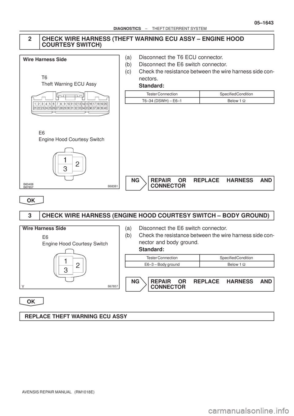
2 CHECK WIRE HARNESS (THEFT WARNING ECU ASSY ± ENGINE HOOD
COURTESY SWITCH)
(a) Disconnect the T6 ECU connector.
(b) Disconnect the E6 switch connector.
(c) Check the resistance between the wire harness side con-
nectors.
Standard:
Tester ConnectionSpecified Condition
T6±34 (DSWH) ± E6±1Below 1 �
NG REPAIR OR REPLACE HARNESS AND
CONNECTOR
OK
3 CHECK WIRE HARNESS (ENGINE HOOD COURTESY SWITCH ± BODY GROUND)
(a) Disconnect the E6 switch connector.
(b) Check the resistance between the wire harness side con-
nector and body ground.
Standard:
Tester ConnectionSpecified Condition
E6±3 ± Body groundBelow 1 �
NG REPAIR OR REPLACE HARNESS AND
CONNECTOR
OK
REPLACE THEFT WARNING ECU ASSY
Page 1742 of 5135
I35707
1AZ±FSE
D5
DLC3
TC
CG13
4W±L
W±B
W±B W±LW±L
W±BW±L
TC 20
E12 17 3
DB DC
CB CA36 DBB
B
A J21 J20J8
J8
J16
J/C
IOIP Center J/B Driver Side J/BECM
*2: RHD *1: LHD (*1)(*1)
(*1)(*2)
(*2)
(*2)
(*1) (*2)
(*2) J/B
A
W±B
± DIAGNOSTICSCRUISE CONTROL SYSTEM
05±1729
AVENSIS REPAIR MANUAL (RM1018E)
DIAGNOSIS CIRCUIT
CIRCUIT DESCRIPTION
Making short circuit between terminal TC and CG of DLC3 will output DTC from the DLC3.
WIRING DIAGRAM
05C4V±01
Page 1743 of 5135
I35707
1CD±FTV
D5
DLC3
TC
CG13
4W±L
W±B
W±B W±LW±L
W±BW±L
TC 11
E12 17 3
DB DC
CB CA36 DBB
B
A J21 J20J8
J8
J16
J/C
ILIP Center J/B Driver Side J/BECM
*2: RHD *1: LHD (*1)(*1)
(*1)(*2)
(*2)
(*2)
(*1) (*2)
(*2) J/B
A
W±B
C52361
TC D5
DLC3
CG
05±1730
± DIAGNOSTICSCRUISE CONTROL SYSTEM
AVENSIS REPAIR MANUAL (RM1018E)
INSPECTION PROCEDURE
1 INSPECT DLC3(TC TERMINAL VOLTAGE)
(a) Turn the ignition switch to the ON position.
(b) Measure the voltage according to the value(s) in the table
below.
Standard:
Tester ConnectionSpecified Condition
TC (D5 ± 13) ± CG (D5 ± 4)10 to 14 V
NG Go to step 3
OK
Page 1744 of 5135

2CHECK HARNESS AND CONNECTOR(DLC3 ± ECM)
(a)Disconnect the ECM connector.
(b)Measure")
C52361
TCD5
DLC3
C52361CG
D5
DLC3
±
DIAGNOSTICS CRUISE CONTROL SYSTEM
05±1731
AVENSIS REPAIR MANUAL (RM1018E)
2CHECK HARNESS AND CONNECTOR(DLC3 ± ECM)
(a)Disconnect the ECM connector.
(b)Measure the resistance according to the value(s) in the
table below.
Standard:
1AZ±FSE
Tester ConnectionSpecified Condition
TC (D5 ± 13) ± TC (E12 ± 20)1 � or less
1CD±FTV
Tester ConnectionSpecified Condition
TC (D5 ± 13) ± TC (E12 ± 11)1 � or less
(c)Measure the resistance according to the value(s) in the
table below.
Standard:
Tester ConnectionSpecified Condition
TC (E12 ± 20) ± Body ground10 k�or higher
TC (E12 ± 11) ± Body ground10 k �or higher
NGREPAIR OR REPLACE HARNESS OR
CONNECTOR
OK
REPLACE ECM (See page 01±32)
3 CHECK HARNESS AND CONNECTOR(DLC3 ± BODY GROUND)
(a) Disconnect the ECM connector.
(b) Measure the resistance according to the value(s) in the table below.
Standard:
Tester ConnectionSpecified Condition
CG (D5 ± 4) ± Body ground10 k�or higher
NG REPAIR OR REPLACE HARNESS OR
CONNECTOR
OK
Page 1745 of 5135
C52361
TCD5
DLC3
05±1732
±
DIAGNOSTICS CRUISE CONTROL SYSTEM
AVENSIS REPAIR MANUAL (RM1018E)
4CHECK HARNESS AND CONNECTOR(DLC3 ± ECM)
(a)Disconnect the ECM connector.
(b)Measure the resistance according to the value(s) in the table below.
Standard:
1AZ±FSE
Tester ConnectionSpecified Condition
TC (D5 ± 13) ± TC (E12 ± 20)1 � or less
1CD±FTV
Tester ConnectionSpecified Condition
TC (D5 ± 13) ± TC (E12 ± 11)1 � or less
(c)Measure the resistance according to the value(s) in the
table below.
Standard:
Tester ConnectionSpecified Condition
TC (E12 ± 20) ± Body ground10 k�or higher
TC (E12 ± 11) ± Body ground10 k �or higher
NGREPAIR OR REPLACE HARNESS OR
CONNECTOR
OK
REPLACE ECM (See page 01±32)
Page 1746 of 5135
I35709
C9
Clutch Start
SW Assy
R±W R±W
R±W R±W
R±W
W±B W±B LG±B
LG±BLG±B
LG±BLG±B
LG±B (*1)
(*2)12 9
515
6
21
568
610 J14
J/C
J19
J/C
DECM
E11
DD
6
IP CPU
CRUISEC11
C11CD
CKCE
CA Center J/B Combination Meter AssyIE2
IR1IE2
IR1 (*1) (*1) (*1) (*1)
CC
(*2)
(*2)(*2)
(*2)
*1: LHD
*2: RHD 1AZ±FSE (M/T) 05±1722
± DIAGNOSTICSCRUISE CONTROL SYSTEM
AVENSIS REPAIR MANUAL (RM1018E)
CRUISE MAIN INDICATOR LIGHT CIRCUIT
CIRCUIT DESCRIPTION
When the cruise control main switch is turned off, the cruise control does not operate.
WIRING DIAGRAM
05C4U±01
Page 1747 of 5135
I35708
R±W
R±W
R±W
W±BW±B LG±BLG±BLG±B
3
710
21
567
610 J/C
DECM
E11
8
D
6
IP C11
C11CD
CKCA
CA Center J/B Combination Meter AssyIK2
(*1)
(*2) C
*1: LHD
*2: RHD 1AZ±FSE (A/T)
RB
DL N1
Park/neutral Position SW
IK1
R±W(*1)(*2)
CPU CRUISE1
CD CA DA DBDCD
J14J14 J19 J19
Center J/B
Driver Side J/B
R±W GAUGE2 GAUGE1
27 7 1
I35710
C9
Clutch Start
SW Assy
R±W R±W
R±W
R±W
R±W
W±B W±BLG±B
LG±BLG±B
(*1)
(*2)1 9
515
6
21
56
8
610
DECM
E11
6
IP CPU
CRUISEC11
C11CD
CKCE
CA Center J/B Combination Meter AssyIE2
IR1IE2
IR1 (*1) (*1) (*1)
(*2)
(*2)
*1: LHD
*2: RHD 1CD±FTV
LG±B
(*2) 2
± DIAGNOSTICSCRUISE CONTROL SYSTEM
05±1723
AVENSIS REPAIR MANUAL (RM1018E)

Pushed
(OFF)
05±1642
± DIAGNOSTICSTHEFT DETERRENT SYSTEM
AVENSIS REPAIR MANUAL (RM1")
(*1)
(*1)(*2)
(*2)
(*")
(*1)
(*1)(*2)
(*2)
(*")

4CHECK HARNESS AND CONNECTOR(DLC3 ± ECM)
(a)Disconnect the ECM connector.
(b)Measure the resistance ac")

(*2)12 9
515
6
21
568
610 J14
J/C
J19
J/C
DECM
E11
DD
6
IP CPU
CRUISEC11
C11CD
CKCE
CA Center")

(*2) C
*1: LHD
*2: RHD 1AZ±FSE (A/T)
RB
DL N1
Park/ne")