Page 1482 of 5135

PROBLEM SYMPTOMS TABLE
RADIO RECEIVER ASSY
SymptomSuspect AreaSee page
Pressing power switch does not start system.5. P")
0549M±11
05±1412
±
DIAGNOSTICS AUDIO SYSTEM
AVENSIS REPAIR MANUAL (RM1018E)
PROBLEM SYMPTOMS TABLE
RADIO RECEIVER ASSY
SymptomSuspect AreaSee page
Pressing power switch does not start system.5. Power source circuit (radio receiver assy)05±1413
Sound quality is bad in all modes. (volume is too low)1. Power source circuit (radio receiver assy)
2. Sound quality is bad in all modes (volume is too low)05±1413
05±1415
Noise occurs.±05±1419
Radio broadcast cannot be received. (bad reception)±05±1420
CD cannot be inserted or is ejected right after insertion.1. Power source circuit (radio receiver assy)
2. CD cannot be inserted or is ejected right after insertion05±1413
05±1422
CD cannot be ejected.1. Power source circuit (radio receiver assy)
2. CD cannot be ejected05±1413
05±1424
Sound quality is bad only when CD is played.(volume is too low)±05±1425
CD sound skips.±05±1426
Cassette tape cannot be inserted or played.1. Power source circuit (radio receiver assy)
2. Cassette tape cannot be inserted or played05±1413
05±1428
Cassette tape cannot be ejected.1. Power source circuit (radio receiver assy)
2. Cassette tape cannot be ejected05±1413
05±1429
Sound quality is bad only when playing tape.±05±1430
Tape is tangled due to incorrect tape speed or auto±reverse mal-
function.±05±1431
STEERING PAD SWITCH
SymptomSuspect AreaSee page
A audio system cannot be operated with steering pad switch±05±1432
Page 1483 of 5135

TERMINALS OF ECU
1. RADIO RECEIVER ASSY
Terminal No. (Symbols)Wiring ColorConditionSTD Voltage (V)")
05C4Y±01
I35611
R10 R12 R11 R9
05±1410
± DIAGNOSTICSAUDIO SYSTEM
AVENSIS REPAIR MANUAL (RM1018E)
TERMINALS OF ECU
1. RADIO RECEIVER ASSY
Terminal No. (Symbols)Wiring ColorConditionSTD Voltage (V)
R9±1(FR+) ± R9±7(GND)LG ± BR*1
LG ± W±B*2Audio system is playing
A waveform synchro-
nized with sounds is
output
R9±2(FL+) ± R9±7(GND)P ± BR*1
P ± W±B*2Audio system is playing
A waveform synchro-
nized with sounds is
output
R9±3(ACC) ± R9±7(GND)GR ± BR*1
GR ± W±B*2Ignition switch to ACC10 to 14
R9±4(+B) ± R9±7(GND)L±Y ± BR*1
L±Y ± W±B*2Always10 to 14
R9±5(FR±) ± R9±7(GND)L ± BR*1
L ± W±B*2Audio system is playing
A waveform synchro-
nized with sounds is
output
R9±6(FL±) ± R9±7(GND)V ± BR*1
V ± W±B*2Audio system is playing
A waveform synchro-
nized with sounds is
output
R9±7(GND) ± Body ground
BR*1 ±
Body ground
W±B*2 ±
Body ground
AlwaysContinuity
R9±8(ANT) ± R9±7(GND)B ± BR*1
B ± W±B*2Radio switch ON and AM or FM10 to 14
R9±10(ILL+) ± R9±7(GND)G ± BR*1
G ± W±B*2Light control switch TAIL10 to 14
R10±1(RR+) ± R9±7(GND)B ± BR*1
R ± W±B*2Audio system is playing
A waveform synchro-
nized with sounds is
output
R10±2(RL+) ± R9±7(GND)B ± BR*1
B ± W±B*2Audio system is playing
A waveform synchro-
nized with sounds is
output
R10±3(RR±) ± R9±7(GND)W ± BR*1
W ± W±B*1Audio system is playing
A waveform synchro-
nized with sounds is
output
R10±6(RL±) ± R9±7(GND)Y ± BR*1
Y ± W±B*2Audio system is playing
A waveform synchro-
nized with sounds is
output
R11±6(GND) ± R9±7(GND)W±R ± BR*1
W±R ± W±B*2AlwaysBelow 1.0
R11±7(SW1) ± R9±7(GND)LG ± BR*1
LG ± W±B*2
Steering pad switch not operating.
�SEEK+ switch push
�SEEK± switch push
�VOL+ switch push
�VOL± switch push4 or more
�Approx. 0.5
�Approx. 0.9
�Approx. 2.0
�Approx. 3.4
Page 1484 of 5135
± DIAGNOSTICSAUDIO SYSTEM
05±1411
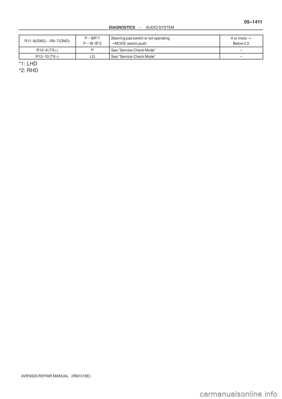
AVENSIS REPAIR MANUAL (RM1018E)R11±8(SW2) ± R9±7(GND)
P ± BR*1
P ± W±B*2Steering pad switch is not operating
�MODE switch push4 or more �
Below 2.5
R12±9 (TX+)PSee ºService Check Modeº±
R12±10 (TX±)LGSee ºService Check Modeº±
*1: LHD
*2: RHD
Page 1485 of 5135
I34723
6
8N4 M2
7
12 3VG
R GB SYNC
VRR VG
G SYNC
VR B W
R G
Y18
3
7
26Navigation ECU
B M2
M2
M2
M2
M2(Shielded) Multi±display
(CRT Display) Display
N4
N4
N4
N4
N4
± DIAGNOSTICSNAVIGATION SYSTEM
05±1477
AVENSIS REPAIR MANUAL (RM1018E)
COLOR ON NAVIGATION SCREEN IS UNUSUAL (RGB SIGNAL
ERROR)
WIRING DIAGRAM
05C3M±01
Page 1486 of 5135
 Display:
Navigation ECU: GVR
VG
G VGVR
B
R
M2
N4
05±1478
±
DIAGNOSTICS NAVIGATION SYSTEM
AVENSIS REPAIR MANUAL (RM1018E)
INSPECTION PROCEDURE
1CHECK HARNESS")
I35666
R
B
Multi±display (CRT Display) Display:
Navigation ECU: GVR
VG
G VGVR
B
R
M2
N4
05±1478
±
DIAGNOSTICS NAVIGATION SYSTEM
AVENSIS REPAIR MANUAL (RM1018E)
INSPECTION PROCEDURE
1CHECK HARNESS AND CONNECTOR(MULTI±DISPLAY (CRT DISPLAY)DISPLAY ± NAVIGATION ECU)
(a)Disconnect the connectors from the multi±display (CRT
display)display and navigation ECU.
(1)Check continuity between the terminals at each
condition, as shown in the chart.
Standard:
Tester connectionSpecified condition
VG ± VGContinuity
VR ± VRContinuity
R ± RContinuity
G ±GContinuity
B ± BContinuity
(2)Check for a short between the terminals at each condition, as shown in the chart.
Standard:
Tester connectionSpecified condition
VG ± Body groundContinuity
VR ± Body groundContinuity
R ± Body groundNo continuity
G ± Body groundNo continuity
B ± Body groundNo continuity
NGREPAIR OR REPLACE HARNESS OR CONNECTOR
OK
2REPLACE MULTI±DISPLAY (CRT DISPLAY) DISPLAY (See page 67±6)
Standard: Normally returns. NG REPLACE NAVIGATION ECU (See page 67±27)
OK
SYSTEM OK
Page 1487 of 5135
I34723
6
8N4 M2
7
12 3VG
R GB SYNC
VRR VG
G SYNC
VR B W
R G
Y18
3
7
26Navigation ECU
B M2
M2
M2
M2
M2(Shielded) Multi±display
(CRT Display) Display
N4
N4
N4
N4
N4
± DIAGNOSTICSNAVIGATION SYSTEM
05±1475
AVENSIS REPAIR MANUAL (RM1018E)
NAVIGATION SCREEN IS NOT STABILIZED (SYNCRONOUS
ERROR)
WIRING DIAGRAM
05C3L±01
Page 1488 of 5135
I35666
Multi±display (CRT Display) Display:Navigation ECU: SYNCVR
VG
SYNC VGVR
M2
N4
05±1476
±
DIAGNOSTICS NAVIGATION SYSTEM
AVENSIS REPAIR MANUAL (RM1018E)
INSPECTION PROCEDURE
1CHECK HARNESS AND CONNECTOR(MULTI±DISPLAY (CRT DISPLAY)DISPLAY ± NAVIGATION ECU)
(a)Disconnect the connectors from the multi±display (CRT
display)display and navigation ECU.
(1)Check continuity between the terminals at each
condition, as shown in the chart.
Standard:
Tester connectionSpecified condition
VG ± VGContinuity
VR ± VRContinuity
SYNC ± SYNCContinuity
(2)Check for a short between the terminals at each condition, as shown in the chart.
Standard:
Tester connectionSpecified condition
VG ± Body groundContinuity
VR ± Body groundContinuity
SYNC ± Body groundNo continuity
NGREPAIR OR REPLACE HARNESS OR CONNECTOR
OK
2REPLACE MULTI±DISPLAY (CRT DISPLAY) DISPLAY (See page 67±6)
Standard: Normally returns. NG REPLACE NAVIGATION ECU (See page 67±27)
OK
SYSTEM OK
Page 1489 of 5135
I34725
Multi±display
(CRT Display) Display
CTX±
CTX+
TX3+
TX3±
GTX+
GTX±M2
M1 M2
M1
M1
M110
5
12
24
5
18LG
V
G±Y
G
P
LG10
5Navigation ECU
Body ECU
(Combination Meter Assy)
Radio Receiver Assy3
4
9
10 C10
C10
R6
R6N4
N4TX±
TX+
TX± TX+
± DIAGNOSTICSNAVIGATION SYSTEM
05±1471
AVENSIS REPAIR MANUAL (RM1018E)
AVC±LAN CIRCUIT
WIRING DIAGRAM
INSPECTION PROCEDURE
1 INSPECT APPARATUS
(a) Choose the apparatus to be inspected.
ApparatusGo to step
Radio receiver assyA
Navigation ECUB
Body ECU (Combination Meter Assy)C
B Go to step 4
C Go to step 6
A
05C3K±01
 Multi±display
(CRT Display) Display
N4
N4
N4
N4
N4
± DIAGNOSTICSNAVIGATION SYSTEM
05�")
 Multi±display
(CRT Display) Display
N4
N4
N4
N4
N4
± DIAGNOSTICSNAVIGATION SYSTEM
05�")
 Display:Navigation ECU: SYNCVR
VG
SYNC VGVR
M2
N4
05±1476
±
DIAGNOSTICS NAVIGATION SYSTEM
AVENSIS REPAIR MANUAL (RM1018E)
INSPECTION PROCEDURE
1CHECK HARNESS AN")
 Display
CTX±
CTX+
TX3+
TX3±
GTX+
GTX±M2
M1 M2
M1
M1
M110
5
12
24
5
18LG
V
G±Y
G
P
LG10
5Navigation ECU
Body ECU
(Combination Meter Assy)
Radio Receiver Assy3")