Page 1103 of 5135
± DIAGNOSTICSELECTRONIC CONTROLLED AUTOMATIC
TRANSAXLE [ECT] (U341E)05±1035
AVENSIS REPAIR MANUAL (RM1018E)
TRANSMISSION CONTROL SWITCH CIRCUIT
CIRCUIT DESCRIPTION
When shifting the shift lever into S range using the transmission control switch, it is possible to shift in 1 to
4 positions.
Shifting º+º once changes up 1 shift range position, º±º once changes down 1 shift range position respective-
ly.
05C8P±01
Page 1104 of 5135
D30750
ECM
SPT1
SFTD
SFTU L
B
R8
30
23 E10
7
1
2
5J17
J/C
W±B(*1)
(*2) A
A S
SFTD
SFTU
E IG 3 R±WT7
Transmission Control SW
Center J/B
Driver Side J/B
I13
Ignition SW
Engine Room J/B No.4
FL MAIN
Battery
*1: LHD
*2 RHDIJIK IPJ15
J/C A AM1 IG1R±W
W±B B±G
G±Y7
1
CA
7
DB
9
DA
1
DH AM1 GAUGE1 IG1 Relay
5
13
2 DN
31
1
4D1
4B ALT
21E10
E10
W±B
W±B
CG
R±W 1
5
DH
G±R
G±Y
W±B
B±G R±W
B±G 05±1036
± DIAGNOSTICSELECTRONIC CONTROLLED AUTOMATIC
TRANSAXLE [ECT] (U341E)
AVENSIS REPAIR MANUAL (RM1018E)
WIRING DIAGRAM
Page 1105 of 5135
![TOYOTA AVENSIS 2005 Service Repair Manual H42584
SPT E1
H42584
SFTU
SFTD E1
H42585
SFTD (+)
E (±) SFTU (+)
± DIAGNOSTICSELECTRONIC CONTROLLED AUTOMATIC
TRANSAXLE [ECT] (U341E)05±1037
AVENSIS REPAIR MANUAL (RM1018E)
INSPECTION PROCEDURE
1 TOYOTA AVENSIS 2005 Service Repair Manual H42584
SPT E1
H42584
SFTU
SFTD E1
H42585
SFTD (+)
E (±) SFTU (+)
± DIAGNOSTICSELECTRONIC CONTROLLED AUTOMATIC
TRANSAXLE [ECT] (U341E)05±1037
AVENSIS REPAIR MANUAL (RM1018E)
INSPECTION PROCEDURE
1](/manual-img/14/57441/w960_57441-1104.png)
H42584
SPT E1
H42584
SFTU
SFTD E1
H42585
SFTD (+)
E (±) SFTU (+)
± DIAGNOSTICSELECTRONIC CONTROLLED AUTOMATIC
TRANSAXLE [ECT] (U341E)05±1037
AVENSIS REPAIR MANUAL (RM1018E)
INSPECTION PROCEDURE
1 CHECK ECM
(a) Turn the ignition switch to ON.
(b) Measure the voltage between terminals SPT and E1 of
the ECM.
OK:
Shift positionSpecified condition
Except S positionBelow 1 V
S position7.5 to 14 V
NG Go to step 6
OK
2 CHECK ECM
(a) Measure the voltage between terminals E1 and that
SFTU as well as SFTD of the ECM.
OK:
Shift positionTester connectionSpecified condition
Shift to º+º
(Up shift)SFTU ± E1Below 1.5 V
S positionSFTU ± E17.5 to 14 V
Shift to º±º
(Down shift)SFTD ± E1Below 1.5 V
S positionSFTD ± E17.5 to 14 V
OK NORMAL
NG
3 INSPECT SHIFT LOCK CONTROL UNIT ASSY(TRANSMISSION CONTROL
SWITCH)
(a) Turn the ignition switch to OFF.
(b) Disconnect the transmission control switch connector.
(c) Measure the resistance between terminals E and that
SFTU as well as SFTD of the transmission control switch
connector.
OK:
Shift positionTester connectionSpecified condition
Shift to º+º
(Up shift)SFTU ± EContinuity
S positionSFTU ± ENo continuity
Shift to º±º
(Down shift)SFTD ± EContinuity
S positionSFTD ± ENo continuity
NG REPLACE SHIFT LOCK CONTROL UNIT ASSY
OK
Page 1106 of 5135
������G25441
SFTUSFTD
SFTD
SFTU
E10
A
05±1038± DIAGNOSTICSELECTRONIC CONTROLLED AUTOMATIC
TRANSAXLE [ECT] (U341E)
AVENSIS REPAIR MANUAL (RM1018E)
4 CHECK HARNESS AND CONNECTOR(ECM ± TRANSMISSION CONTROL
SWITCH)
(a) Disconnect the ECM connector.
(b) Check the continuity between ECM and transmission
control switch.
OK:
Tester connectionSpecified condition
SFTU (E10±23) ± SFTU (A±2)Continuity
SFTD (E10±30) ± SFTD (A±1)Continuity
NG REPAIR OR REPLACE HARNESS AND
CONNECTOR
OK
5 CHECK HARNESS AND CONNECTOR(TRANSMISSION COTROL SWITCH ± BODY
GROUND)
(a) Check the continuity between body ground and E of the transmission control switch connector (wire
harness side).
OK:
Continuity
NG REPAIR OR REPLACE HARNESS AND
CONNECTOR
OK
CHECK AND REPLACE ECM
Page 1107 of 5135
H42585
IG
S
������H42587
SPT (+) E1 (±)
E10
± DIAGNOSTICSELECTRONIC CONTROLLED AUTOMATIC
TRANSAXLE [ECT] (U341E)05±1039
AVENSIS REPAIR MANUAL (RM1018E)
6 INSPECT SHIFT LOCK CONTROL UNIT ASSY(TRANSMISSION CONTROL
SWITCH)
(a) Turn the ignition switch to OFF.
(b) Disconnect the transmission control switch connector.
(c) Check the continuity between terminals IG and S of the
transmission control switch.
OK:
Shift positionTester connectionSpecified condition
Except S positionIG ± SNo continuity
S positionIG ± SContinuity
NG REPLACE SHIFT LOCK CONTROL UNIT ASSY
OK
7 CHECK HARNESS AND CONNECTOR
(a) Connect the transmission control switch connector.
(b) Disconnect the ECM connector.
(c) Turn the ignition switch to ON.
(d) Measure the voltage between terminals SPT and E1 of
the ECM connector.
OK:
Shift positionTester connectionSpecified condition
Except S positionSPT ± E1Below 1 V
S positionSPT ± E17.5 to 14 V
NG REPAIR OR REPLACE HARNESS AND
CONNECTOR
OK
CHECK AND REPLACE ECM
Page 1113 of 5135

I35392
DTCDEF
I35417ECU±B2
Fuse block:
3
2
145678
910111213141516
DLC3
A04550
05±1092
±
DIAGNOSTICS AIR CONDITIONING SYSTEM
AVENSIS REPAIR MANUAL (RM1018E)
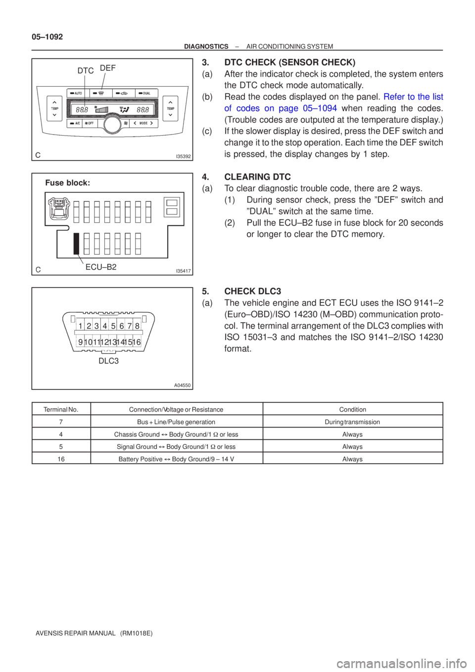
3.DTC CHECK (SENSOR CHECK)
(a)After the indicator check is completed, the system enters the DTC check mode automatically.
(b)Read the codes displayed on the panel. Refer to the list of codes on page 05±1094 when reading the codes.
(Trouble codes are outputed at the temperature display.)
(c) If the slower display is desired, press the DEF switch and
change it to the stop operation. Each time the DEF switch
is pressed, the display changes by 1 step.
4. CLEARING DTC
(a) To clear diagnostic trouble code, there are 2 ways. (1) During sensor check, press the ºDEFº switch andºDUALº switch at the same time.
(2) Pull the ECU±B2 fuse in fuse block for 20 seconds or longer to clear the DTC memory.
5. CHECK DLC3
(a) The vehicle engine and ECT ECU uses the ISO 9141±2 (Euro±OBD)/ISO 14230 (M±OBD) communication proto-
col. The terminal arrangement of the DLC3 complies with
ISO 15031±3 and matches the ISO 9141±2/ISO 14230
format.
Terminal No.Connection/Voltage or ResistanceCondition
7Bus + Line/Pulse generationDuring transmission
4Chassis Ground � Body Ground/1 � or lessAlways
5Signal Ground � Body Ground/1 � or lessAlways
16Battery Positive � Body Ground/9 ± 14 VAlways
Page 1233 of 5135

05C5V±01
3
2
145678
910111213141516
DLC3
A04550
C93955
05±1184
±
DIAGNOSTICS SUPPLEMENTAL RESTRAINT SYSTEM
AVENSIS REPAIR MANUAL (RM1018E)
PRE±CHECK
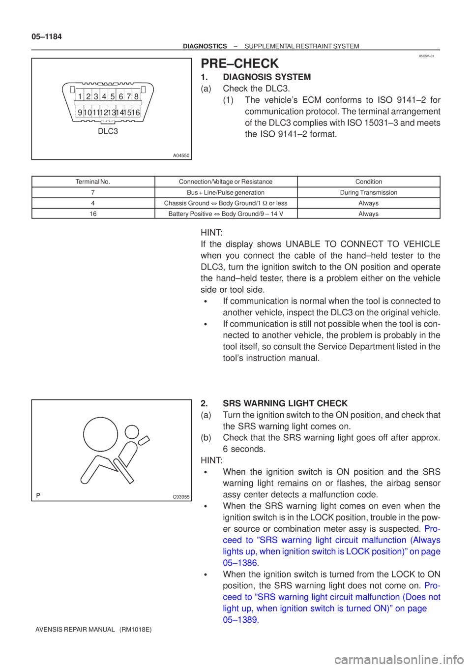
1.DIAGNOSIS SYSTEM
(a)Check the DLC3. (1)The vehicle's ECM conforms to ISO 9141±2 forcommunication protocol. The terminal arrangement
of the DLC3 complies with ISO 15031±3 and meets
the ISO 9141±2 format.
Terminal No.Connection/Voltage or ResistanceCondition
7Bus + Line/Pulse generationDuring Transmission
4Chassis Ground � Body Ground/1 � or lessAlways
16Battery Positive � Body Ground/9 ± 14 VAlways
HINT:
If the display shows UNABLE TO CONNECT TO VEHICLE
when you connect the cable of the hand±held tester to the
DLC3, turn the ignition switch to the ON position and operate
the hand±held tester, there is a problem either on the vehicle
side or tool side.
�If communication is normal when the tool is connected to
another vehicle, inspect the DLC3 on the original vehicle.
�If communication is still not possible when the tool is con-
nected to another vehicle, the problem is probably in the
tool itself, so consult the Service Department listed in the
tool's instruction manual.
2.SRS WARNING LIGHT CHECK
(a)Turn the ignition switch to the ON position, and check that the SRS warning light comes on.
(b)Check that the SRS warning light goes off after approx.
6 seconds.
HINT:
�When the ignition switch is ON position and the SRS
warning light remains on or flashes, the airbag sensor
assy center detects a malfunction code.
�When the SRS warning light comes on even when the
ignition switch is in the LOCK position, trouble in the pow-
er source or combination meter assy is suspected. Pro-
ceed to ºSRS warning light circuit malfunction (Always
lights up, when ignition switch is LOCK position)º on page
05±1386.
�When the ignition switch is turned from the LOCK to ON
position, the SRS warning light does not come on. Pro-
ceed to ºSRS warning light circuit malfunction (Does not
light up, when ignition switch is turned ON)º on page
05±1389.
Page 1418 of 5135

0549J±12
± DIAGNOSTICSAUDIO SYSTEM
05±1405
AVENSIS REPAIR MANUAL (RM1018E)
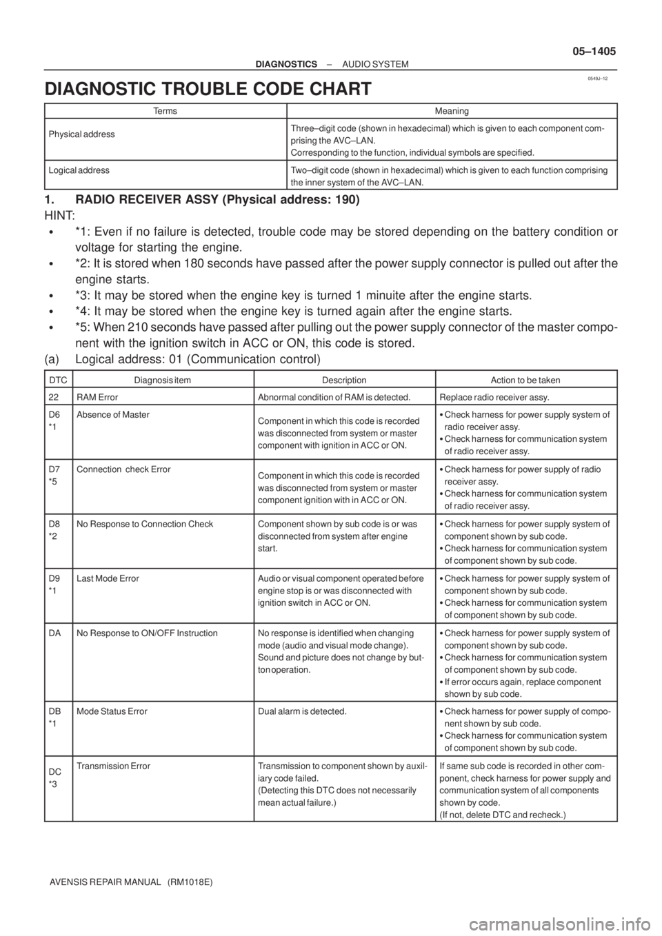
DIAGNOSTIC TROUBLE CODE CHART
TermsMeaning
Physical addressThree±digit code (shown in hexadecimal) which is given to each component com-
prising the AVC±LAN.
Corresponding to the function, individual symbols are specified.
Logical addressTwo±digit code (shown in hexadecimal) which is given to each function comprising
the inner system of the AVC±LAN.
1. RADIO RECEIVER ASSY (Physical address: 190)
HINT:
�*1: Even if no failure is detected, trouble code may be stored depending on the battery condition or
voltage for starting the engine.
�*2: It is stored when 180 seconds have passed after the power supply connector is pulled out after the
engine starts.
�*3: It may be stored when the engine key is turned 1 minuite after the engine starts.
�*4: It may be stored when the engine key is turned again after the engine starts.
�*5: When 210 seconds have passed after pulling out the power supply connector of the master compo-
nent with the ignition switch in ACC or ON, this code is stored.
(a) Logical address: 01 (Communication control)
DTCDiagnosis itemDescriptionAction to be taken
22RAM ErrorAbnormal condition of RAM is detected.Replace radio receiver assy.
D6
*1Absence of MasterComponent in which this code is recorded
was disconnected from system or master
component with ignition in ACC or ON.�Check harness for power supply system of
radio receiver assy.
�Check harness for communication system
of radio receiver assy.
D7
*5Connection check ErrorComponent in which this code is recorded
was disconnected from system or master
component ignition with in ACC or ON.�Check harness for power supply of radio
receiver assy.
�Check harness for communication system
of radio receiver assy.
D8
*2No Response to Connection CheckComponent shown by sub code is or was
disconnected from system after engine
start.�Check harness for power supply system of
component shown by sub code.
�Check harness for communication system
of component shown by sub code.
D9
*1Last Mode ErrorAudio or visual component operated before
engine stop is or was disconnected with
ignition switch in ACC or ON.�Check harness for power supply system of
component shown by sub code.
�Check harness for communication system
of component shown by sub code.
DANo Response to ON/OFF InstructionNo response is identified when changing
mode (audio and visual mode change).
Sound and picture does not change by but-
ton operation.�Check harness for power supply system of
component shown by sub code.
�Check harness for communication system
of component shown by sub code.
�If error occurs again, replace component
shown by sub code.
DB
*1Mode Status ErrorDual alarm is detected.�Check harness for power supply of compo-
nent shown by sub code.
�Check harness for communication system
of component shown by sub code.
DC
*3Transmission ErrorTransmission to component shown by auxil-
iary code failed.
(Detecting this DTC does not necessarily
mean actual failure.)If same sub code is recorded in other com-
ponent, check harness for power supply and
communication system of all components
shown by code.
(If not, delete DTC and recheck.)