Page 4115 of 5135

05CDX−02
05 −1 0
−
DIAGNOSTICS SFI SYSTEM (2AZ−FSE)
AVENSIS Supplement (RM 1045E)
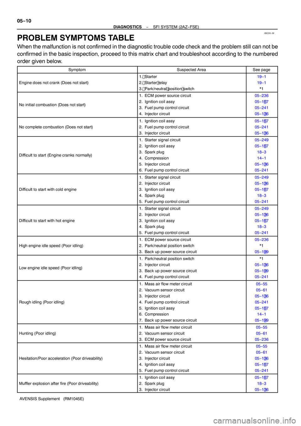
PROBLEM SYMPTOMS TABLE
When the malfunction is not confirmed in the diagnostic trouble code check and the problem still can not be
confirmed in the basic inspection, proceed to this matrix chart and troubleshoot according to the numbered
order given below.
SymptomSuspected AreaSee page
Engine does not crank (Does not start)
1. Starter
2. Starter relay
3. Park/neutral position switch19 −1
1 9 −1
* 1
No initial combustion (Does not start)
1 . ECM power source circuit
2. Ignition coil assy
3. Fuel pump control circuit
4. Injector circuit05 −236
05 −1 67
05 −24 1
05 −1 36
No complete combustion (Does not start)
1. Ignition coil assy
2. Fuel pump control circuit
3. Injector circuit05 −1 67
05 −24 1
05 −1 36
Difficult to start (Engine cranks normally)
1. Starter signal circuit
2. Ignition coil assy
3. Spark plug
4. Compression
5. Injector circuit
6. Fuel pump control circuit05 −249
05 −1 67
1 8 − 3
1 4 −1
05 −1 36
05 −24 1
Difficult to start with cold engine
1. Starter signal circuit
2. Injector circuit
3. Ignition coil assy
4. Spark plug
5. Fuel pump control circuit05 −249
05 −1 36
05 −1 67
1 8 − 3
05 −24 1
Difficult to start with hot engine
1. Starter signal circuit
2. Injector circuit
3. Ignition coil assy
4. Spark plug
5. Fuel pump control circuit05 −249
05 −1 36
05 −1 67
1 8 − 3
05 −24 1
High engine idle speed (Poor idling)
1. ECM power source circuit
2. Park/neutral position switch
3. Back up power source circuit05 −236
* 1
05 −1 99
Low engine idle speed (Poor idling)
1. Park/neutral position switch
2. Injector circuit
3. Back up power source circuit
4. Fuel pump control circuit* 1
05 −1 36
05 −1 99
05 −24 1
Rough idling (Poor idling)
1. Mass air flow meter circuit
2. Vacuum sensor circuit
3. Injector circuit
4. Fuel pump control circuit
5. Ignition coil assy
6. Compression
7. Back up power source circuit05 −55
05 −61
05 −1 36
05 −24 1
05 −1 67
1 4 −1
05 −1 99
Hunting (Poor idling)
1. Mass air flow meter circuit
2. Vacuum sensor circuit
3. ECM power source circuit05 −55
05 −61
05 −236
Hesitation/Poor acceleration (Poor driveability)
1. Mass air flow meter circuit
2. Vacuum sensor circuit
3. Injector circuit
4. Ignition coil assy
5. Fuel pump control circuit05 −55
05 −61
05 −1 36
05 −1 67
05 −24 1
Muffler explosion after fire (Poor driveability)
1. Ignition coil assy
2. Spark plug
3. Injector circuit05 −1 67
1 8 − 3
05 −1 36
Page 4116 of 5135
−
DIAGNOSTICS SFI SYSTEM (2AZ−FSE)
05 −11
AVENSIS Supplement (RM 1045E)
Symptom
See page
Suspected Area
Surging (Poor driveability)1 . Spark plug
2. Injector circuit1 8 − 3
05 −1 36
Engine stalls soon after starting1. Mass air flow meter circuit
2. Vacuum sensor circuit05 −55
05 −61
Engine stalls after accelerator pedal depressed1. Mass air flow meter circuit
2. Vacuum sensor circuit05 −55
05 −61
Engine stalls after accelerator pedal release
1. Mass air flow meter circuit
2. Vacuum sensor circuit
3. ECM05 −55
05 −61
05 −1 2
Engine stalls during A/C operation1. A/C signal circuit (Compressor circuit)
2. ECM* 1
05 −1 2
Engine stalls when shifting from N to D1. Park/neutral position switch*1
*1: See page 40 −8 of Pub. No. RM 1018E AVENSIS.
Page 4117 of 5135

05HHY−01
05 −8
−
DIAGNOSTICS SFI SYSTEM (2AZ−FSE)
AVENSIS Supplement (RM 1045E)
BASIC INSPECTION
When the malfunction is not confirmed in the DTC check, troubleshooting should be carried out in all the
possible circuits considered as causes of the problem. In many cases, by carrying out the basic engine check
shown in the following flowchart, the location causing the problem can be found quickly and efficiently. There-
fore, using this check is essential in the engine troubleshooting.
1 CHECK BATTERY VOLTAGE
NOTICE:
Carry out this check with the engine stopped and ignition switch OFF.
OKNG
Voltage11 V or moreLess than 11 V
NG CHARGE OR REPLACE BATTERY
OK
2 CHECK IF ENGINE WILL CRANK
NG PROCEED TO PROBLEM SYMPTOMS TABLE ON PAGE 05 −1 0
OK
3 CHECK IF ENGINE STARTS
NG GO TO STEP 7
OK
4 CHECK AIR FILTER
(a) Visually check that the air filter is not excessively dirty or oily. NG REPLACE AIR FILTER
OK
5 CHECK IDLE SPEED (See page 14−1 )
NG PROCEED TO PROBLEM SYMPTOMS TABLE
ON PAGE 05 −1 0
OK
Page 4122 of 5135
05−4
−
DIAGNOSTICS SFI SYSTEM (2AZ−FSE)
AVENSIS Supplement (RM 1045E)
9 SYMPTOM SIMULATION
1 0 DTC CHECK (See page 05 −1 9)
AMalfunction code
BNo code
B GO TO STEP 12
A
11 DTC CHART (See page 05 −31)
GO TO STEP 14
12 BASIC INSPECTION (See page 05 −8)
AWrong parts not confirmed
BWrong parts confirmed
B GO TO STEP 17
A
1 3 PROBLEM SYMPTOMS TABLE (See page 05 −1 0)
AWrong circuit confirmed
BWrong parts confirmed
B GO TO STEP 17
A
1 4 CHECK ECM POWER SOURCE CIRCUIT (See page 05 −236)
1 5 CIRCUIT INSPECTION
AMalfunction not confirmed
BMalfunction confirmed
B GO TO STEP 18
A
Page 4124 of 5135

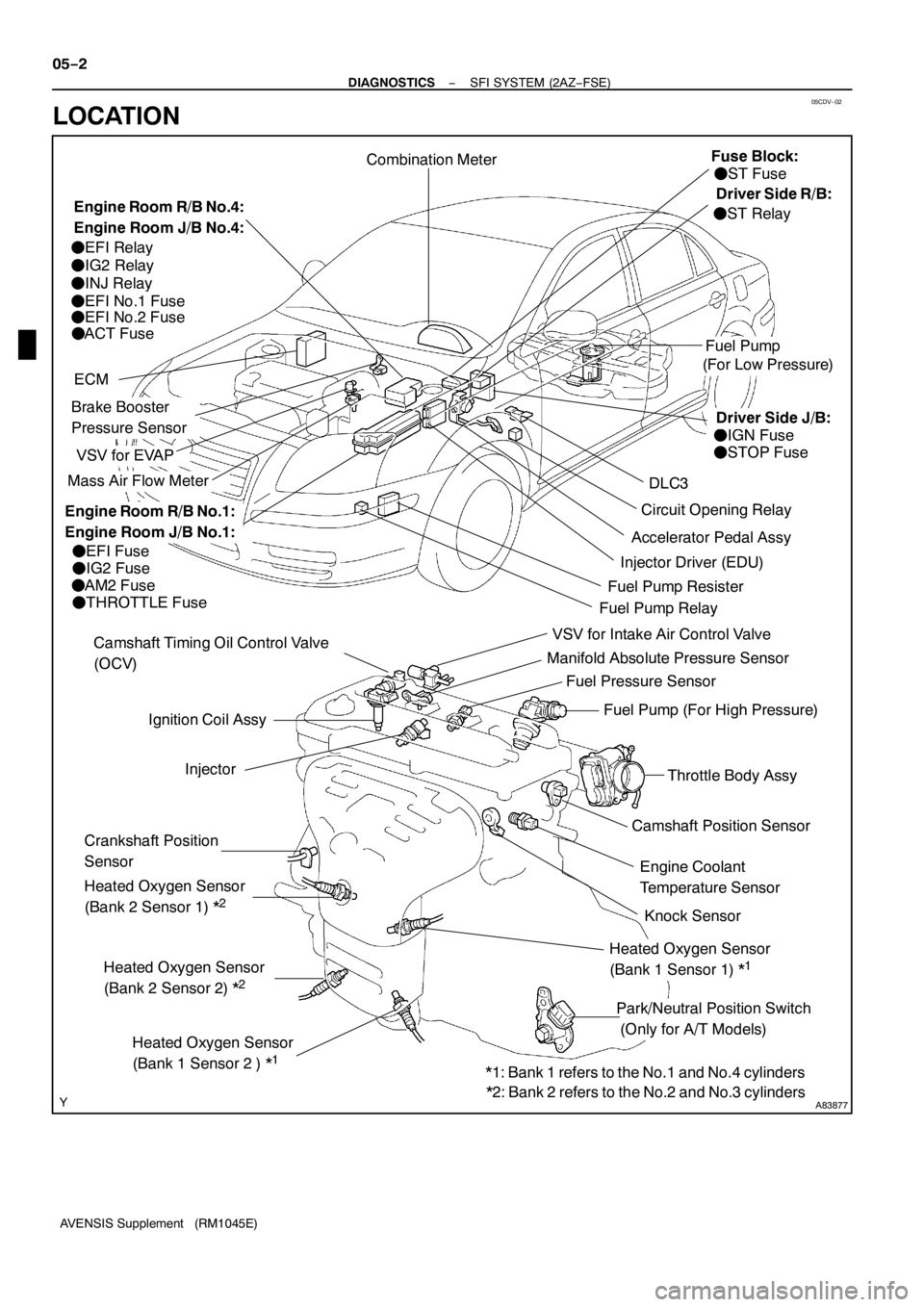
05CDV−02
A83877
Ignition Coil Assy
Camshaft Position Sensor
VSV for EVAP
Combination Meter
DLC3
VSV for Intake Air Control Valve
Fuel Pump
ECM
Knock Sensor Camshaft Timing Oil Control Valve
(OCV)
Injector
Crankshaft Position
Sensor
Park/Neutral Position Switch
(Only for A/T Models)Engine Coolant
Temperature Sensor
Mass Air Flow Meter
Throttle Body Assy
Accelerator Pedal Assy
Heated Oxygen Sensor
(Bank 2 Sensor 2) *
2
Circuit Opening Relay
Heated Oxygen Sensor
(Bank1Sensor 2 ) *
1
Heated Oxygen Sensor
(Bank 2 Sensor1)*
2
Heated Oxygen Sensor
(Bank1Sensor1)*
1
Manifold Absolute Pressure Sensor
Fuel Pump (For High Pressure)
Injector Driver (EDU)
Brake Booster
Pressure Sensor
Fuel Pressure Sensor
(For Low Pressure)
FEFI Fuse
FIG2 Fuse
FAM2 Fuse
FTHROTTLE Fuse
FEFI Relay
FIG2 Relay
FINJ Relay
FEFI No.1Fuse
FEFI No.2 Fuse
FACT Fuse
FST Fuse
FIGN Fuse
FSTOP Fuse
FST Relay
Fuel Pump RelayFuel Pump Resister
*1: Bank1refers to the No.1and No.4 cylinders
*2: Bank 2 refers to the No.2 and No.3 cylinders
Engine Room R/B No.4:
Engine Room J/B No.4:Fuse Block:
Engine Room R/B No.1:
Engine Room J/B No.1:
Driver Side R/B:
Driver Side J/B: 05−2
− DIAGNOSTICSSFI SYSTEM (2AZ−FSE)
AVENSIS Supplement (RM1045E)
LOCATION
Page 4129 of 5135

A76882
Battery FL MAINIGN
B−G11
E9
2 6
Engine
Room
J/B No.4Engine Room
R/B No.1
AM2
1 2
B−G4
18Driver
Side J/B
B−W B−R
WECM
DH
DA B−R
B−R 1
1A 1
1
4A
1 4B(LHD) (RHD)IP1 IE41
1
I13
Ignition Switch
AM2
IG2
(LHD)J8C
(RHD)J26A
(LHD)J8C
(RHD)J26AB−WCheck
Engine
Warning
LightW
C11
Combination Meter
229
J/C Engine Room
J/B No.1
− DIAGNOSTICSSFI SYSTEM (2AZ−FSE)
05−251
AVENSIS Supplement (RM1045E)
CHECK ENGINE WARNING LIGHT CIRCUIT
CIRCUIT DESCRIPTION
The CHK ENG is used to indicate the ECM’s detection of a vehicle malfunction.
The instrument panel IGN fuse provides the circuit power and the ECM provides the circuit ground that illumi-
nates the CHK ENG.
CHK ENG operations should be checked visually:
The CHK ENG should be illuminated when the ignition is first turned to ON. If the CHK ENG is always ON
or OFF, use the hand−held tester and follow the procedures below to determine the cause of the problem.
WIRING DIAGRAM
INSPECTION PROCEDURE
HINT:
Troubleshoot each trouble symptom in accordance with the chart below.
CHK ENG remains onStart inspection from step1
CHK ENG is not illuminatedStart inspection from step 3
05CJB−02
Page 4130 of 5135

A67445ECM ConnectorW
E9
05
−252
−
DIAGNOSTICS SFI SYSTEM (2AZ−FSE)
AVENSIS Supplement (RM 1045E)
1 CLEAR DTC
(a) Connect the hand −held tester to the DLC 3.
(b) Turn the ignition switch to ON and turn the hand −held tester ON.
(c) Read the DTC (see page 05 −1 9) .
(d) Clear the DTC (see page 05 −1 9) .
(e) Check that the CHK ENG is not illuminated. Standard: CHK ENG is not illuminated
OK REPAIR CIRCUIT INDICATED BY OUTPUT DTC(See page 05 −7)
NG
2 CHECK HARNESS AND CONNECTOR(CHECK FOR SHORT IN WIRE HARNESS)
(a) Disconnect the E9 ECM connector.
(b) Turn the ignition switch to ON.
(c) Check that the CHK ENG is not illuminated. Standard: CHK ENG is not illuminated
(d) Reconnect the ECM connector.
NG CHECK AND REPAIR HARNESS AND CONNECTOR
OK
REPLACE ECM (See page 10− 65 of Pub. No. RM 1018E AVENSIS)
3 CHECK CHK ENG CONDITION
(a) Check that the CHK ENG is illuminated when turning the ignition switch to ON.
Standard: CHK ENG is illuminated
OK SYSTEM OK
NG
4 INSPECT COMBINATION METER ASSY(CHK ENG CIRCUIT)
(a) See the combination meter troubleshooting procedure on page 05 −1 0.
NG REPAIR OR REPLACE BULB OR COMBINATION METER ASSEMBLY
OK
CHECK AND REPAIR HARNESS AND CONNECTOR (COMBINATION METER −ECM)
Page 4131 of 5135

−
DIAGNOSTICS SFI SYSTEM (2AZ−FSE)
05 −249
AVENSIS Supplement (RM 1045E)
STARTER SIGNAL CIRCUIT
CIRCUIT DESCRIPTION
When the engine is cranked, the intake air flow is slow, so fuel vaporization is poor. A rich mixture is therefore
necessary in order to achieve good startability. While the engine is being cranked, the battery voltage is ap-
plied to terminal STA of the ECM. The starter signal is mainly used to increase the fuel injection volume for
the starting injection control and after −start injection control.
WIRING DIAGRAM
Refer to DTC P06 17 on page 05 −203.
INSPECTION PROCEDURE
HINT:
This diagnostic troubleshooting procedure is on the premise that the engine is being cranked under normal
conditions. If the engine does not crank, proceed to the problem symptoms table on page 05 −1 0.
1 READ VALUE OF HAND −HELD TESTER(STARTER SIGNAL)
(a) Connect the hand −held tester to the DLC3.
(b) Turn the ignition switch to ON and turn the hand −held tester ON.
(c) On the hand −held tester, select the item: DIAGNOSIS / OBD/MOBD / DATA LIST / ALL / STARTER
SIG. Read the values.
Result:
Ignition Switch PositionONSTART
STA SignalOFFON
OK PROCEED TO NEXT CIRCUIT INSPECTION SHOWN IN PROBLEM SYMPTOMS TABLE
(See page 05 −1 0)
NG
05CJC −02