2005 SUZUKI JIMNY rear seat
[x] Cancel search: rear seatPage 45 of 687
Downloaded from www.Manualslib.com manuals search engine 0B-14 MAINTENANCE AND LUBRICATION
3) Rotate tires.
For details, refer to “Tire Rotation” in Section 3F.
WHEEL DISCS INSPECTION
Inspect each wheel disc for dents, distortion and cracks. A disc in
badly damaged condition must be replaced.
WHEEL BEARING INSPECTION
1) Check front wheel bearing for wear, damage, abnormal
noise or rattles. For details, refer to “Wheel Disc, Nut and
Bearing Check” in Section 3D.
2) Check rear wheel bearing for wear, damage, abnormal noise
or rattles. For details, refer to “Wheel Disc, Nut and Bearing
Check” in Section 3E.
Suspension System
INSPECTION
Check suspension bolts and nuts for tightness and retighten them
as necessary.
Repair or replace defective parts, if any.
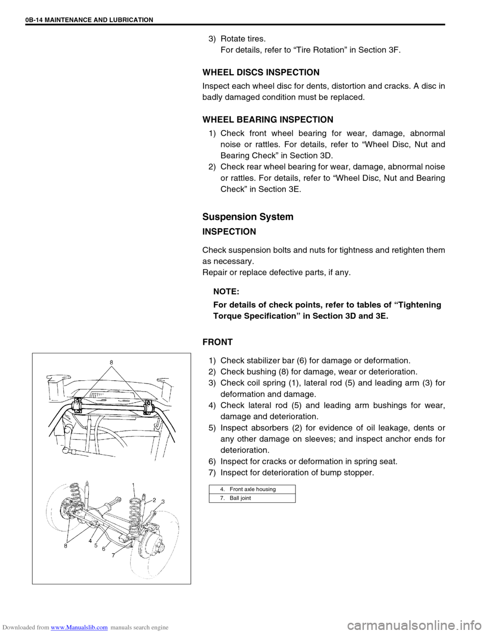
FRONT
1) Check stabilizer bar (6) for damage or deformation.
2) Check bushing (8) for damage, wear or deterioration.
3) Check coil spring (1), lateral rod (5) and leading arm (3) for
deformation and damage.
4) Check lateral rod (5) and leading arm bushings for wear,
damage and deterioration.
5) Inspect absorbers (2) for evidence of oil leakage, dents or
any other damage on sleeves; and inspect anchor ends for
deterioration.
6) Inspect for cracks or deformation in spring seat.
7) Inspect for deterioration of bump stopper.NOTE:
For details of check points, refer to tables of “Tightening
Torque Specification” in Section 3D and 3E.
4. Front axle housing
7. Ball joint
Page 46 of 687
Downloaded from www.Manualslib.com manuals search engine MAINTENANCE AND LUBRICATION 0B-15
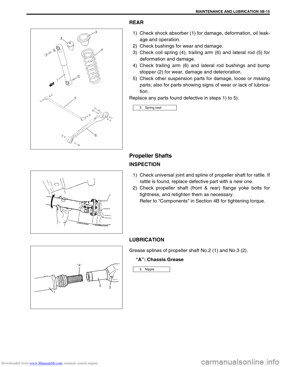
REAR
1) Check shock absorber (1) for damage, deformation, oil leak-
age and operation.
2) Check bushings for wear and damage.
3) Check coil spring (4), trailing arm (6) and lateral rod (5) for
deformation and damage.
4) Check trailing arm (6) and lateral rod bushings and bump
stopper (2) for wear, damage and deterioration.
5) Check other suspension parts for damage, loose or missing
parts; also for parts showing signs of wear or lack of lubrica-
tion.
Replace any parts found defective in steps 1) to 5).
Propeller Shafts
INSPECTION
1) Check universal joint and spline of propeller shaft for rattle. If
rattle is found, replace defective part with a new one.
2) Check propeller shaft (front & rear) flange yoke bolts for
tightness, and retighten them as necessary.
Refer to “Components” in Section 4B for tightening torque.
LUBRICATION
Grease splines of propeller shaft No.2 (1) and No.3 (2).
“A”: Chassis Grease
3. Spring seat
3. Nipple
Page 114 of 687

Downloaded from www.Manualslib.com manuals search engine STEERING, SUSPENSION, WHEELS AND TIRES 3-5
Tire Diagnosis
Irregular and/or Premature Wear
Irregular and premature wear has many possible causes. Some
of them are: incorrect inflation pressures lack of tire rotation, driv-
ing habits, improper alignment.
If the following conditions are noted rotation is in order:
Front tire wear is different from rear.
Uneven wear exists across the tread of any tire.
Left front and right front tire wear is unequal.
Left rear and right rear tire wear is unequal.
There is cupping, flat spotting, etc.
A wheel alignment check is in order if the following conditions are
noted:
Left front and right front tire wear is unequal.
Wear is uneven across the tread of any front tire.
Front tire treads have scuffed appearance with “feather”
edges on one side of tread ribs or blocks.
Wear Indicators
The original equipment tires have built-in tread wear indicators to
show when tires need replacement. These indicators will appear
as 12 mm (0.47 inch) wide bands when the tire tread depth
becomes 1.6 mm (0.063 inch). When the indicators appear in 3 or
more grooves at 6 locations, tire replacement is recommended.
Radial Tire Waddle
Waddle is side to side movement at the front and/or rear of the
vehicle. It is caused by the steel belt not being straight within the
tire. It is most noticeable at low speed, 5 to 30 mph. It is possible
to road test a vehicle and tell on which end of the vehicle the
faulty tire is located. If the waddle tire is on the rear, the rear end
of the vehicle will shake from side to side or “waddle”. From the
driver’s seat it feels as though someone is pushing on the side of
the vehicle. If the faulty tire is on the front, the waddle is more
visual. The front sheet metal appears to be moving back and forth
and the driver feels as though he is at the pivot point in the vehi-
cle. Waddle can be quickly diagnosed by using a Tire Problem
Detector (TPD) and following the equipment manufacturer’s rec-
ommendations.
If a TPD is not available, the more time consuming method of sub-
stituting known good tire / wheel assemblies on the problem vehi-
cle can be used as follows:
[A] : Hard cornering, under inflation or lack of tire rotation
[B] : Incorrect wheel alignment, tire construction not uniform or wheel heavy acceleration
Page 220 of 687

Downloaded from www.Manualslib.com manuals search engine REAR SUSPENSION 3E-1
6F1
6F2
6G
1A
6K
7A
7A1
7B1
3E
8A
8B
8A
8B
8C
8D
8E
9
10
10A
10B
SECTION 3E
REAR SUSPENSION
CONTENTS
General Description ....................................... 3E-2
Diagnosis ........................................................ 3E-3
Diagnosis Table ........................................... 3E-3
Rear Shock Absorber Check ........................ 3E-3
Trailing Arm, Lateral Rod, Axle Housing
and Coil Spring Check ................................. 3E-3
Trailing Arm and Lateral Rod Bush Check ... 3E-3
Rear Suspension Fasteners ......................... 3E-4
Bearing Retainer and Axle Shaft Oil Seal
Check ........................................................... 3E-4
Bump Stopper and Spring Rubber Seat
Check ........................................................... 3E-4
Wheel Disc, Nut and Bearing Check ............ 3E-4On-Vehicle Service ........................................ 3E-5
Rear Shock Absorber................................... 3E-5
Coil Spring ................................................... 3E-6
Bump Stopper .............................................. 3E-9
Lateral Rod .................................................. 3E-9
Trailing Arm / Bushing................................ 3E-10
Rear Axle Shaft and Wheel Bearing .......... 3E-12
Rear Axle Shaft Inner Oil Seal ................... 3E-17
Rear Axle Housing ..................................... 3E-18
Tightening Torque Specifications .............. 3E-22
Required Service Materials ......................... 3E-22
Special Tools ................................................ 3E-23
WARNING:
When hoisting vehicle, be sure to select the lifting point suitable for the service work referring to Sec-
tion 0A.
NOTE:
All suspension fasteners are an important attaching part in that it could affect the performance of
vital parts and systems, and/or could result in major repair expense. They must be replaced with
one of the same part number or with an equivalent part if replacement becomes necessary. Do not
use a replacement part of lesser quality or substitute design. Torque values must be used as speci-
fied during reassembly to assure proper retention of this part.
Never attempt to heat, quench or straighten any suspension part. Replace it with a new part, or
damage to the part may result.
Page 223 of 687

Downloaded from www.Manualslib.com manuals search engine 3E-4 REAR SUSPENSION
Rear Suspension Fasteners
Check each bolt and nut fastening suspension parts for tightness.
Tighten loose one, if any, to specified torque, referring to “Tighten-
ing Torque Specifications” of this section.
Bearing Retainer and Axle Shaft Oil Seal
Check
When brake drum has been removed, check inside of brake
drum for gear oil leakage.
Also, check backside of brake back plate for oil leakage.If oil
leakage is found, replace defective oil seal.
Whenever it is possible to check oil seal during disassembly,
check its lip for wear.
If oil leakage or worn lip is found, replace defective oil seal.
Bump Stopper and Spring Rubber Seat Check
Inspect for wear and breakage. If found defective, replace.
Wheel Disc, Nut and Bearing Check
Inspect each wheel disc for dents, distortion and cracks. A
disc in badly damaged condition must be replaced.
Check wheel hub nuts for tightness and, as necessary,
retighten to specification.
Tightening torque
Wheel nuts
(a) : 95 N·m (9.5 kg-m, 69.0 lb-ft)
Page 226 of 687

Downloaded from www.Manualslib.com manuals search engine REAR SUSPENSION 3E-7
4) Remove shock absorber lower mounting bolt (2).
5) Lower rear axle housing (2) gradually as far down as where
coil spring (1) can be removed.
6) Remove coil spring (1).
7) Remove spring rubber seat (1).
1. Shock absorber
Page 227 of 687
Downloaded from www.Manualslib.com manuals search engine 3E-8 REAR SUSPENSION
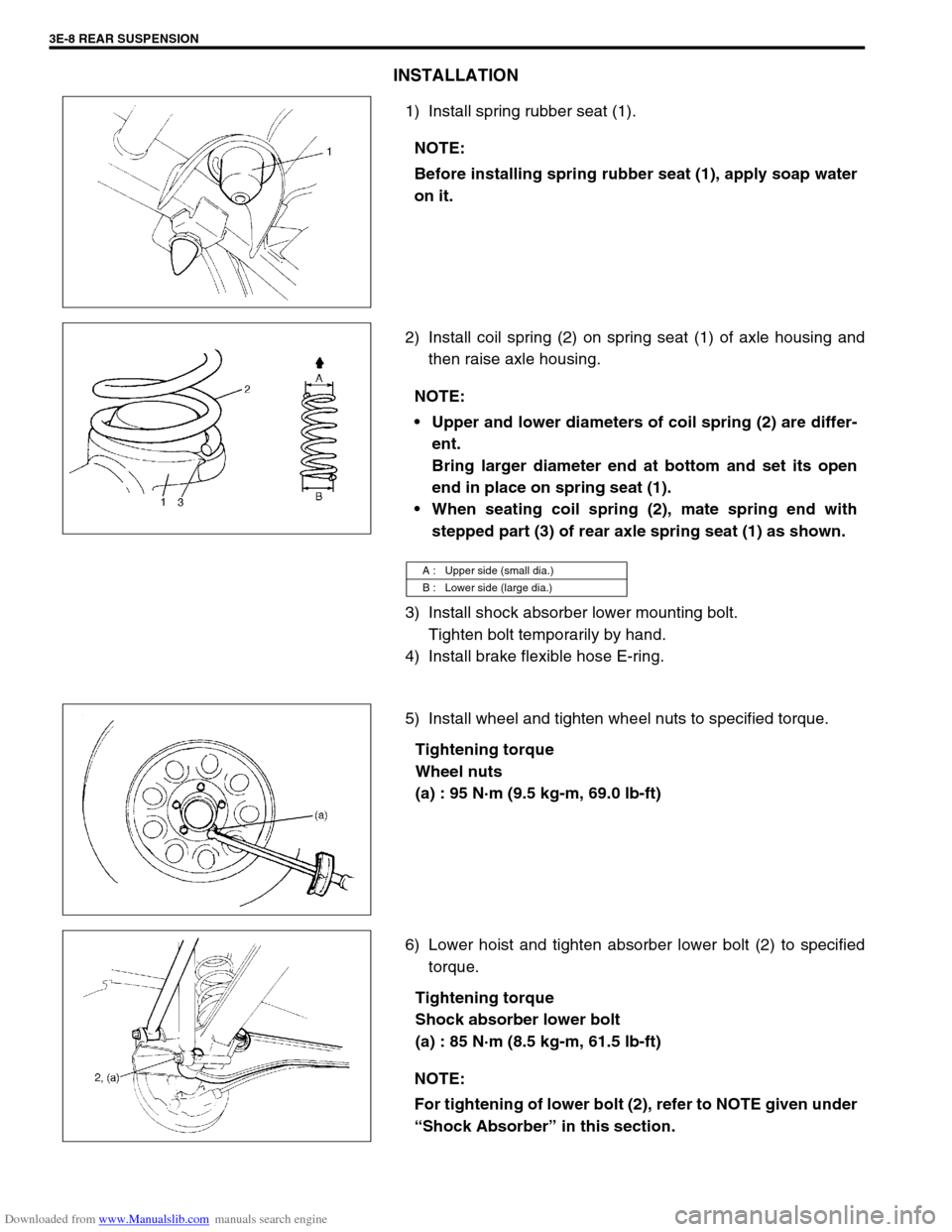
INSTALLATION
1) Install spring rubber seat (1).
2) Install coil spring (2) on spring seat (1) of axle housing and
then raise axle housing.
3) Install shock absorber lower mounting bolt.
Tighten bolt temporarily by hand.
4) Install brake flexible hose E-ring.
5) Install wheel and tighten wheel nuts to specified torque.
Tightening torque
Wheel nuts
(a) : 95 N·m (9.5 kg-m, 69.0 lb-ft)
6) Lower hoist and tighten absorber lower bolt (2) to specified
torque.
Tightening torque
Shock absorber lower bolt
(a) : 85 N·m (8.5 kg-m, 61.5 lb-ft) NOTE:
Before installing spring rubber seat (1), apply soap water
on it.
NOTE:
Upper and lower diameters of coil spring (2) are differ-
ent.
Bring larger diameter end at bottom and set its open
end in place on spring seat (1).
When seating coil spring (2), mate spring end with
stepped part (3) of rear axle spring seat (1) as shown.
A : Upper side (small dia.)
B : Lower side (large dia.)
NOTE:
For tightening of lower bolt (2), refer to NOTE given under
“Shock Absorber” in this section.
Page 238 of 687
Downloaded from www.Manualslib.com manuals search engine REAR SUSPENSION 3E-19
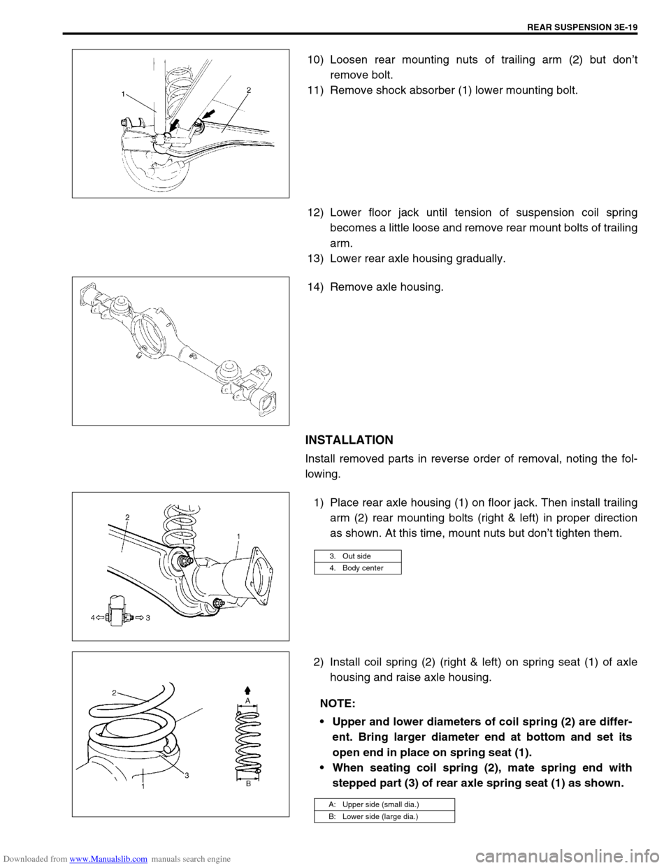
10) Loosen rear mounting nuts of trailing arm (2) but don’t
remove bolt.
11) Remove shock absorber (1) lower mounting bolt.
12) Lower floor jack until tension of suspension coil spring
becomes a little loose and remove rear mount bolts of trailing
arm.
13) Lower rear axle housing gradually.
14) Remove axle housing.
INSTALLATION
Install removed parts in reverse order of removal, noting the fol-
lowing.
1) Place rear axle housing (1) on floor jack. Then install trailing
arm (2) rear mounting bolts (right & left) in proper direction
as shown. At this time, mount nuts but don’t tighten them.
2) Install coil spring (2) (right & left) on spring seat (1) of axle
housing and raise axle housing.
3. Out side
4. Body center
NOTE:
Upper and lower diameters of coil spring (2) are differ-
ent. Bring larger diameter end at bottom and set its
open end in place on spring seat (1).
When seating coil spring (2), mate spring end with
stepped part (3) of rear axle spring seat (1) as shown.
A: Upper side (small dia.)
B: Lower side (large dia.)