Page 218 of 687
Downloaded from www.Manualslib.com manuals search engine FRONT SUSPENSION 3D-45
Special Tool
09917-47910 09913-50121 09913-65210 09913-75520
Vacuum pump gauge Oil seal remover Tie rod end remover Bearing installer
09951-76010 09924-74510 09942-15510 09943-35511 or 09943-
35512
Bearing installer Bearing installer handle Sliding hammer Brake drum remover
09944-66010 09944-68510 09951-16050 09944-77020
Wheel hub / knuckle oil
seal installerBearing installer attach-
mentWheel bearing tightening
toolRing nut wrench
09944-78210 09917-88210 09916-58210 09922-55131
Bearing installer support Valve guide installer
attachmentValve guide installer han-
dleBearing installer
Page 249 of 687

Downloaded from www.Manualslib.com manuals search engine 3F-6 WHEELS AND TIRES
Maintenance and Minor Adjustments
Wheel and Tire
Wheel repairs that use welding, heating, or peening are not approved. All damaged wheels should be replaced.
Studs
If a broken stud is found, see Section 3E (rear) or Section 3D (front) for Note and Replacement procedure.
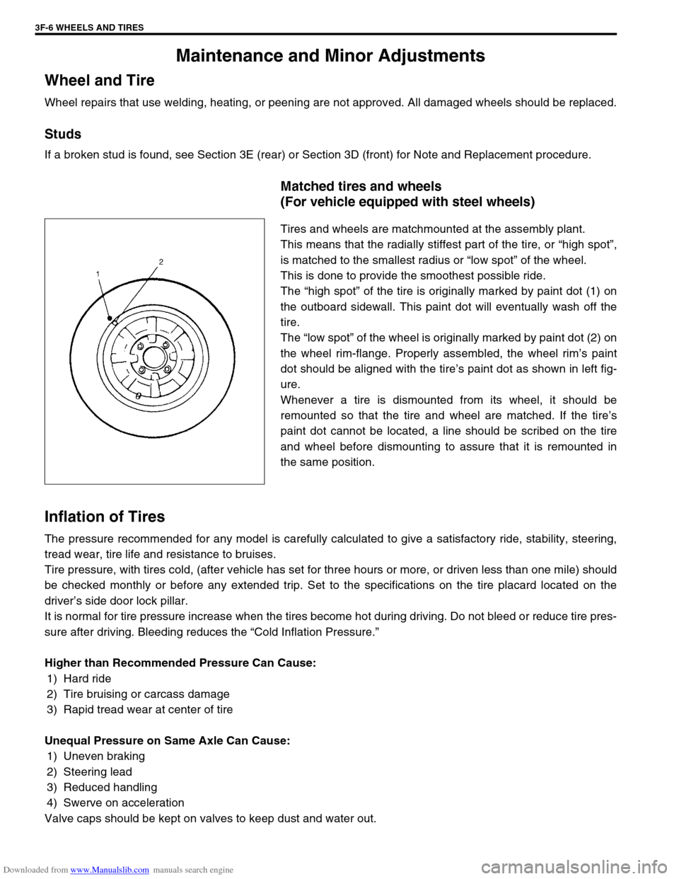
Matched tires and wheels
(For vehicle equipped with steel wheels)
Tires and wheels are matchmounted at the assembly plant.
This means that the radially stiffest part of the tire, or “high spot”,
is matched to the smallest radius or “low spot” of the wheel.
This is done to provide the smoothest possible ride.
The “high spot” of the tire is originally marked by paint dot (1) on
the outboard sidewall. This paint dot will eventually wash off the
tire.
The “low spot” of the wheel is originally marked by paint dot (2) on
the wheel rim-flange. Properly assembled, the wheel rim’s paint
dot should be aligned with the tire’s paint dot as shown in left fig-
ure.
Whenever a tire is dismounted from its wheel, it should be
remounted so that the tire and wheel are matched. If the tire’s
paint dot cannot be located, a line should be scribed on the tire
and wheel before dismounting to assure that it is remounted in
the same position.
Inflation of Tires
The pressure recommended for any model is carefully calculated to give a satisfactory ride, stability, steering,
tread wear, tire life and resistance to bruises.
Tire pressure, with tires cold, (after vehicle has set for three hours or more, or driven less than one mile) should
be checked monthly or before any extended trip. Set to the specifications on the tire placard located on the
driver’s side door lock pillar.
It is normal for tire pressure increase when the tires become hot during driving. Do not bleed or reduce tire pres-
sure after driving. Bleeding reduces the “Cold Inflation Pressure.”
Higher than Recommended Pressure Can Cause:
1) Hard ride
2) Tire bruising or carcass damage
3) Rapid tread wear at center of tire
Unequal Pressure on Same Axle Can Cause:
1) Uneven braking
2) Steering lead
3) Reduced handling
4) Swerve on acceleration
Valve caps should be kept on valves to keep dust and water out.
Page 252 of 687

Downloaded from www.Manualslib.com manuals search engine WHEELS AND TIRES 3F-9
Tire
Mounting and demounting
Use tire changing machine to mount or demount tires. Follow equipment manufacturer’s instructions. Do not use
hand tools or tire irons alone to change tires as they may damage tire beads or wheel rim.
Rim bead seats should be cleaned with wire brush or coarse steel wool to remove lubricants, old rubber and
light rust. Before mounting or demounting tire, bead area should be well lubricated with approved tire lubricant.
After mounting, inflate to 240 kPa (35 psi) so that beads are completely seated. Then adjust pressure to speci-
fied shown on tire placard.
Install valve core and inflate to proper pressure.
Repair
There are many different materials and techniques on the market to repair tires. As not all of these work on all
types of tires, tire manufacturers have published detailed instructions on how and when to repair tires. These
instructions can be obtained from the tire manufacturer.WARNING:
Do not stand over tire when inflating. Bead may break when bead snaps over rim’s safety hump and
cause serious personal injury.
Do not exceed 240 kPa (35 psi) pressure when inflating. If 240 kPa (35 psi) pressure will not seat
beads, deflate, re-lubricate and reinflate. Over inflation may cause bead to break and cause serious
personal injury.
Page 263 of 687

Downloaded from www.Manualslib.com manuals search engine 5-2 BRAKES
Master Cylinder ............................................ 5-38
Fill Reservoir ................................................ 5-40
LSPV (Load Sensing Proportioning Valve)
Assembly (If Equipped) ................................. 5-42
LSPV Assembly ........................................... 5-43
P (Proportioning) Valve ................................. 5-44
Brake Booster ................................................ 5-45
Inspection and adjustment ....................... 5-46
Brake Hose/Pipe .......................................... 5-48Front brake hose/pipe ............................... 5-48
Rear Brake Hose/Pipe .................................. 5-51
Parking Brake Lever/Cable ........................... 5-52
Parking brake lever ................................... 5-52
Parking Brake Cable ..................................... 5-53
Tightening Torque Specifications ................. 5-54
Required Service Material.............................. 5-54
Special Tool .................................................... 5-55
Page 264 of 687

Downloaded from www.Manualslib.com manuals search engine BRAKES 5-3
General Description
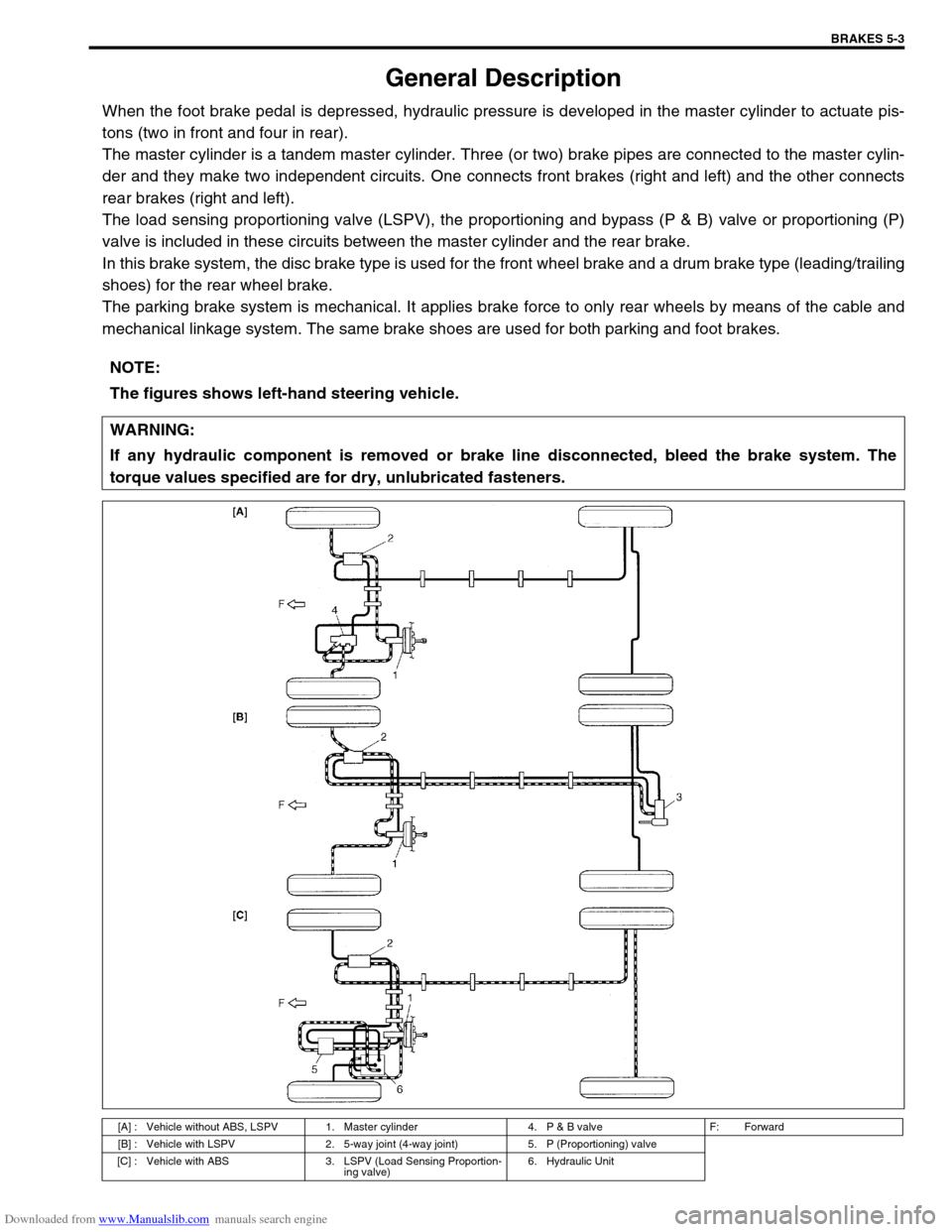
When the foot brake pedal is depressed, hydraulic pressure is developed in the master cylinder to actuate pis-
tons (two in front and four in rear).
The master cylinder is a tandem master cylinder. Three (or two) brake pipes are connected to the master cylin-
der and they make two independent circuits. One connects front brakes (right and left) and the other connects
rear brakes (right and left).
The load sensing proportioning valve (LSPV), the proportioning and bypass (P & B) valve or proportioning (P)
valve is included in these circuits between the master cylinder and the rear brake.
In this brake system, the disc brake type is used for the front wheel brake and a drum brake type (leading/trailing
shoes) for the rear wheel brake.
The parking brake system is mechanical. It applies brake force to only rear wheels by means of the cable and
mechanical linkage system. The same brake shoes are used for both parking and foot brakes.
NOTE:
The figures shows left-hand steering vehicle.
WARNING:
If any hydraulic component is removed or brake line disconnected, bleed the brake system. The
torque values specified are for dry, unlubricated fasteners.
[A] : Vehicle without ABS, LSPV 1. Master cylinder 4. P & B valve F: Forward
[B] : Vehicle with LSPV 2. 5-way joint (4-way joint) 5. P (Proportioning) valve
[C] : Vehicle with ABS 3. LSPV (Load Sensing Proportion-
ing valve)6. Hydraulic Unit
Page 268 of 687
Downloaded from www.Manualslib.com manuals search engine BRAKES 5-7
Brake warning light
turns on when brake
is appliedBrake fluid leaking from brake line Investigate leaky point, correct it
and add brake fluid.
Insufficient amount of brake fluid Add brake fluid.
Faulty P & Differential valve (Differential switch) Replace.
Brake warning light
fails to turn on even
when parking brake is
appliedBulb burnt out Replace bulb.
Brake warning light circuit open Repair circuit.
ABS warning light
does not turn on for 2
sec. after ignition
switch has turned ON.Bulb burnt out Replace bulb.
ABS warning light circuit open, if equipped with
ABS (including check relay)Check system referring to “TABLE-
A” in Section 5E.
ABS warning light
remains on after igni-
tion switch has turned
on for 2 sec.Malfunctioning ABS, if equipped with ABS Check system referring to “TABLE-
B” in Section 5E. Condition Possible Cause Correction
Page 298 of 687

Downloaded from www.Manualslib.com manuals search engine BRAKES 5-37
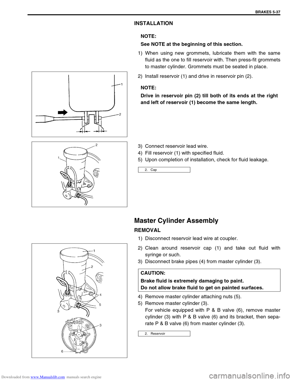
INSTALLATION
1) When using new grommets, lubricate them with the same
fluid as the one to fill reservoir with. Then press-fit grommets
to master cylinder. Grommets must be seated in place.
2) Install reservoir (1) and drive in reservoir pin (2).
3) Connect reservoir lead wire.
4) Fill reservoir (1) with specified fluid.
5) Upon completion of installation, check for fluid leakage.
Master Cylinder Assembly
REMOVAL
1) Disconnect reservoir lead wire at coupler.
2) Clean around reservoir cap (1) and take out fluid with
syringe or such.
3) Disconnect brake pipes (4) from master cylinder (3).
4) Remove master cylinder attaching nuts (5).
5) Remove master cylinder (3).
For vehicle equipped with P & B valve (6), remove master
cylinder (3) with P & B valve (6) and its bracket, then sepa-
rate P & B valve (6) from master cylinder (3). NOTE:
See NOTE at the beginning of this section.
NOTE:
Drive in reservoir pin (2) till both of its ends at the right
and left of reservoir (1) become the same length.
2. Cap
CAUTION:
Brake fluid is extremely damaging to paint.
Do not allow brake fluid to get on painted surfaces.
2. Reservoir
Page 303 of 687

Downloaded from www.Manualslib.com manuals search engine 5-42 BRAKES
LSPV (Load Sensing Proportioning Valve) Assembly (If Equipped)
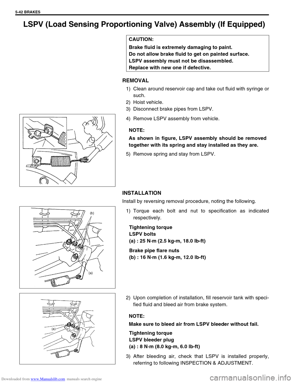
REMOVAL
1) Clean around reservoir cap and take out fluid with syringe or
such.
2) Hoist vehicle.
3) Disconnect brake pipes from LSPV.
4) Remove LSPV assembly from vehicle.
5) Remove spring and stay from LSPV.
INSTALLATION
Install by reversing removal procedure, noting the following.
1) Torque each bolt and nut to specification as indicated
respectively.
Tightening torque
LSPV bolts
(a) : 25 N·m (2.5 kg-m, 18.0 lb-ft)
Brake pipe flare nuts
(b) : 16 N·m (1.6 kg-m, 12.0 lb-ft)
2) Upon completion of installation, fill reservoir tank with speci-
fied fluid and bleed air from brake system.
Tightening torque
LSPV bleeder plug
(a) : 8 N·m (8.0 kg-m, 6.0 lb-ft)
3) After bleeding air, check that LSPV is installed properly,
referring to following INSPECTION & ADJUSTMENT. CAUTION:
Brake fluid is extremely damaging to paint.
Do not allow brake fluid to get on painted surface.
LSPV assembly must not be disassembled.
Replace with new one if defective.
NOTE:
As shown in figure, LSPV assembly should be removed
together with its spring and stay installed as they are.
NOTE:
Make sure to bleed air from LSPV bleeder without fail.